The author's experience of over 30 years of publishing assemblies, in addition to the classes he teaches, shows that problems with the functioning of devices assembled by readers and students always have the same origins. Of course, we do not rule out cases in which the diagrams or boards themselves may contain errors introduced during the design process and which sometimes escape our review.
We always take care when assembling the published devices, many of which often do not work on their own, as their settings may be part of another project, which is not always understood by those who see something assembled, apparently “exactly like” the original, but which does not work. If this happens, what should be done? What could have happened?
Let's analyze the most common cases:
a) Always check your assembly against the diagram and then against the printed circuit board drawing.
In the projects we present in our magazine, it is common to include the values of the components that are repeated in the bill of materials along with the diagram, along with additional information such as working voltage for the capacitors, dissipation and color code for the resistors, etc.
This way, if there is a discrepancy between the values, the reader can have a starting point for a possible failure. Then check if the resistors and capacitors have the correct values in the assembly.
It is very common for a 1k resistor to be placed in place of a 10k in an assembly. Brown, black, red can easily be confused with brown, black, orange, especially if the red of the first one is faded. For capacitors, the problem is more serious due to the codes used.
It is common to swap component values, for example using 4k7 = 4,700 pF instead of 4K7 = 4.7 pF in an assembly, which causes it to not work. Figure 1 shows some ceramic capacitor codes that cause confusion.
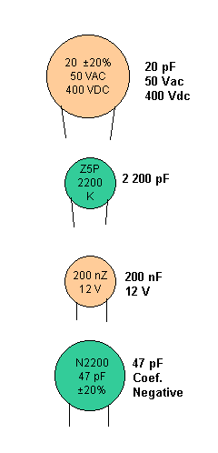
Checking the values of the components in an assembly with a lens is essential, even before powering the circuit for a functional test.
b) Component types and specifications
The type of component indicated for an application is essential for its operation, especially in the most critical cases. This occurs, for example, in high-frequency circuits (transmitters, receivers, oscillators, etc.) where there are functions in which the use of ceramic capacitors is mandatory. If, in the function indicated for a ceramic capacitor, a polyester capacitor is used, even if it has the same value as the one ordered, the circuit may not work.
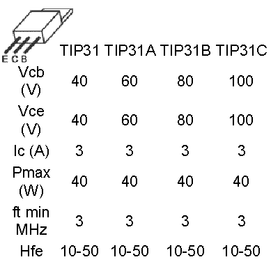
For transistors, diodes, SCRs and other semiconductors, in some cases a suffix may be indicated that means an additional characteristic. For example, for transistors, the last letter can mean both the gain and the working voltage, and this should be observed when purchasing the component. For example, the TIP31A is different from the TIP31 because the “A” means that this transistor supports a higher voltage, as shown in figure 2.
Similarly, the BC548B has a higher gain than the BC548.
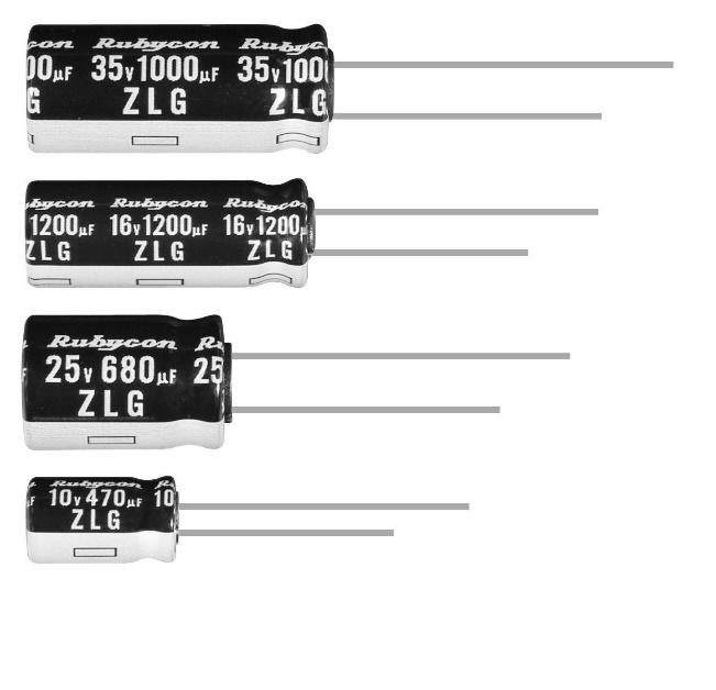
If we use a common BC548 where a BC548B is recommended, we may have operating problems with the device being assembled. There are also cases in which minimum voltages and currents are specified. For capacitors, it is common to indicate the working voltage. In Figure 3, we have some capacitors with their working voltages indicated.
This is the maximum voltage they support and not the voltage they appear when in operation. Therefore, if a circuit has voltages up to about 12 V, it is common to use capacitors of at least 16 V (in places where 12 V may appear), thus providing a tolerance for safe operation.
If a capacitor with a lower voltage is used, its dielectric may break, “burning” and preventing the device from working. The same applies to currents. In a circuit where we have a current of less than 1 A, we can use a diode that supports 1 A or more. It is also necessary to pay attention to dissipation, that is, the amount of heat that the component can dissipate.
If we use a 1/8 W resistor where a 1 W resistor is required, it will overheat and may burn. Resistors have their dissipation associated with their size, as shown in figure 4.
This list also includes components that must be “assembled” at home. This is the case of coils, which are extremely critical elements in transmitters and receivers. If the number of turns, separation between turns, diameter and characteristics of the core are not followed, the circuit will not oscillate at the correct frequency.
c) Position of polarized components
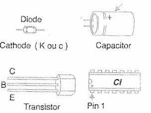
Diodes, transistors, electrolytic capacitors, SCRs and integrated circuits have correct positions for their assembly. If they are reversed, the device will certainly not work and, more than that, the component itself may burn out. Normally, the positions of the components are indicated in the drawings of the printed circuit boards, but in cases where the reader designs the board himself, he must know the format and arrangement of the terminals to know how to position each component. Figure 5 shows how the positions of the polarized components are indicated.
d) Soldas frias
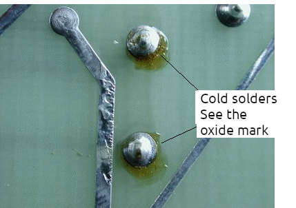
This is, without a doubt, the biggest cause of electronic devices not working. We call “cold solder” when it “doesn’t stick”. The component appears to be soldered, but if we examine it with a lens we see that it is loose, that the solder has not adhered to its terminals or to the printed circuit board. Result: the current cannot pass and therefore the device does not work.
The most common case occurs when we solder enameled wires from coils to a board. These wires need to be scraped before being soldered, because the thin layer of enamel that covers them prevents the solder from adhering. Figure 6 shows some cases of cold solder.
e) PCB design
When designing a printed circuit board, several problems can occur.
The first is interruption and short circuits between tracks when the board is corroded. Interruptions can be repaired with a solder bridge and short circuits eliminated with a utility knife. Figure 7 shows some imperfections in the design of printed circuit boards.
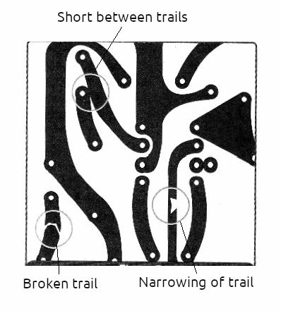
In any case, before assembling, examine all the tracks on the board with a magnifying glass to make sure they are perfect. Another problem that can occur is a poorly designed board. “Forgotten” tracks can mean a missing connection between components that will prevent the device from working.
Check the board assembly against the diagram, and do this at least twice!
There are also assemblies that are critical in terms of the layout and width of the tracks. Tracks that work with high frequency signals must be short and cannot have right-angled curves (corners). Tracks that work with high currents must be wide.
The general rule is that for each ampere of current, the track must be 1 mm wide. In a 3 A source, the tracks that carry the main current must be at least 3 mm wide.
f) Tolerances
This is the factor that greatly influences the operation of certain devices, especially the most critical ones. Controlling the action of component tolerances is quite difficult, especially when the components used are purchased from regular stores or taken from other equipment. What happens is that when designing a circuit or assembling a prototype, common components are used that may have high tolerances.
For example, resistors can have tolerances of 5% to 20%, while electrolytic capacitors can have tolerances of up to 40%. This means that if we add up the deviations of the values of all the resistors in a circuit, if by chance they all have deviations in the same direction, the circuit may be led to a condition in which it becomes impossible to function.
For transistors, the problem can be even more serious. A BC548 transistor can have gains between 110 and 800. If, by chance, the assembler of an experimental project uses a transistor with a gain of 500, therefore within the range, and manages to make it work poorly. Another assembler who uses the same transistor, but with a gain of 200 (still within the range), will not be able to make the same circuit work!
There is also an aggravating factor for the use of transistors: a general-purpose transistor can be “re-stamped”. There are dishonest suppliers who buy batches of transistors that do not pass factory tests because their characteristics are below those required and re-stamped them with general-purpose type designations such as BC548, 2N2222, 2N3904, etc. and sell them.
In less critical applications, they work, but if a higher gain is required, the buyer will “dance”. The correct thing to do (we usually do this in our projects) is to calculate the circuit for the transistor at the minimum gain condition.
In any case, when faced with a circuit that does not oscillate, has low gain or still presents instability, one possibility of solving the problem is to replace the transistor, even for an identical one that may have a higher gain...
Many multimeters have transistor tests that indicate the gain and there are also transistor testers. Figure 8 shows a transistor tester.

It would be interesting to have one of them.
g) Reliable supplier, reliable components
Obviously, problems with the supply of components with different characteristics than those required, of poor origin or even “re-stamped”, can be avoided with a reliable supplier.
h) Adjustments
Many projects require critical adjustments to be put into operation. Although in magazines aimed at readers who do not have the resources to purchase complicated instruments, most adjustments can be made without instruments or at most with a multimeter, there are certain precautions to be taken into account.
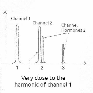
The main problem that occurs with adjustments is in oscillator and high frequency circuits. It is common for the assembler to adjust a circuit not to its correct frequency but to a multiple frequency, that is, a harmonic. When this happens, the circuit works, but its performance is much lower than expected.
In a transmitter, for example, the range will be reduced and the assembler will have difficulty knowing why. In a tone recognizer on a remote control, for example, the circuit becomes unstable and begins to respond to inappropriate commands, as shown in Figure 9.
Finally, we have the loss of selectivity of the circuits that begin to “mix” stations. The best procedure in this case is to try to readjust the control element in another position (trimmer, trimpot, etc.).
i) Similar configurations
Electronic circuits follow configurations that always have the same arrangement of components. Transistors, for example, always have load elements (resistors, coils, etc.), bias resistors and coupling and decoupling capacitors, as shown in Figure 10.
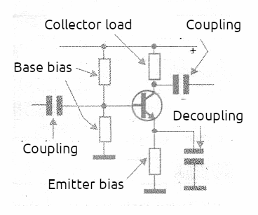
Look for a similar circuit and see if the values are compatible, if that is how the connection should be made, the polarity of the power supply, etc. If the configuration uses a popular integrated circuit such as the 555, check other articles or diagrams to see if the connections are similar for that function. They can serve as a reference, including giving an order of magnitude of the components used.
j) Suspicion Meter
Another “tool” that is very important when assembling an electronic circuit and it doesn’t work is the “suspicion meter”.
If something goes wrong, suspect everything.
Remember that, according to Murphy’s Law, the very thing that has the least chance of failing or being wrong is what is causing the problem in your assembly...
Check everything! Even the things that you are sure are not the cause of the problem...
k) Seeking help
Obviously, the first place the reader thinks of to ask for help is our technical team. However, in order for us to help without seeing the assembly (which is impossible for us – since we are unable to examine each project that is sent to us individually), the reader must be able to explain what he or she did.
Many readers send us long letters describing imprecisely what is happening with their devices, which makes it very difficult for us to provide any assistance. In order for the reader to have their query effectively answered and in a way that can help, proceed as follows:
• Be objective in your query – it should be short and direct to make it easier for us to examine it.
• Always indicate where on the website the article you assembled is located. Preferably give the name.
• Explain clearly what is happening with it: it does not work, it does not adjust, it does not have range.
• Indicate if you used any component with specifications different from those indicated in the list of materials.
• Indicate if you changed component values.
• If any component heats up or burns out, indicate which one.
• If you have a multimeter, indicate the voltages that you can measure at the main points of the circuit.
It is also important to point out that our correspondence is voluminous.
Therefore, do not expect a query sent in the morning to already have a response in the afternoon. We need time to analyze the problem, locate the article and, of course, serve the readers who are in front of you.
We also need to inform you that we are not in a position to change published projects to meet the reader's needs. "How can I modify amplifier X, article Y so that it becomes a popcorn maker?"
We also cannot give opinions on commercial equipment or suggest changes. This is because changes and modifications are not always simple and possible. Even when they are possible, we cannot suggest something to the reader without trying it or being sure that it works!

