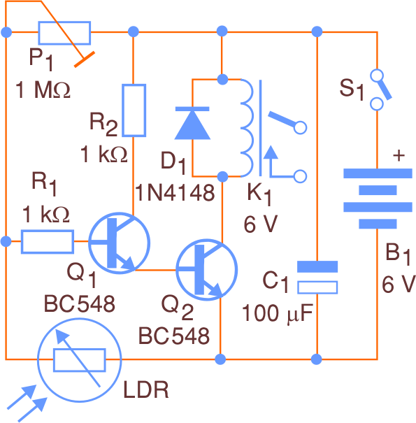
We describe the assembly of an educational project that serves to illustrate how a circuit that activates a relay works when the light affecting a sensor is interrupted or when it goes dark. The circuit is powered by plugs and especially suitable for mounting on a contact matrix or printed circuit board. The photoelectric circuit presented here is also ideal for school trips or civic festivals. In truth, this circuit is part of our book Projects for Civil Festivals (see in the national books on this site). The relay indicated in the original design is for a current of at least 2 A, but this component can be tripped by others of greater current capacity.
6 V relays from Metaltex are the ideals for this application, but any other rated to 6V x 50 mA can be used. The circuit power supply is 6 V and the sensor is a highly sensitive common LDR. This sensitivity can be adjusted according to the application, using a potentiometer. Under the condition that the relay is deenergized, the consumption is very low. With the relay activated, the current drained from the source is about 100 mA. It is clear that the consumption will be lower if relayed with lower power supplies previously used. For example, with 12 V relays and power supply at the same voltage, the maximum current will be around 50 mA. For greater direction and sensitivity, the LDR can be installed in a tube with a converging lens on the front. In figure 1 here is the complete diagram of the appliance.

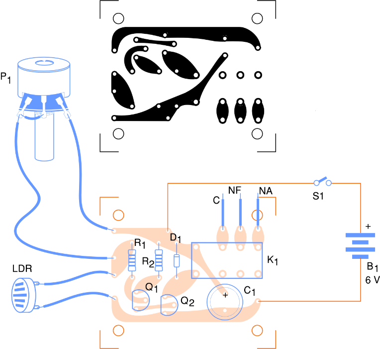
The layout of the components on the printed circuit board is shown in figure 2.
Please note that the panel was developed based on the format of a relay based on DIL (Dual in Line). If you use a different relay, you must alter the circuit board printed in accordance with the base of the filled relay. The transistors admit equivalents and the LDR can be connected to the circuit through long insulated strings, at least 10 meters of compression. The S1 interrupter is optional if the appliance is used in demonstrations, since to unplug we can simply remove the support plugs. To test the appliance, turn on the power supply and adjust P1 to ensure that the relay is permanently deactivated using the LDR incident light. When the light decreases or is shortened, the relay must be activated. List of relay contacts on the equipment you want to control. They function as an interrupter. When assembling, carefully observe the position of the components, mainly transistors and diodes, since if otherwise inverted the circuit will not work.
The charge is connected to the relay contacts, for example, a lamp. This lamp will be powered by the mains or by the lamps, as appropriate. The relay functions are turned on as an on-off switch and unplugged from the lamp. If the charge is connected between C and NA, the charge will be connected when the relay is switched on. If the charge is connected between C and NF, the charge will be disconnected when the relay is switched on.
By finding the P1 position with the LDR, the circuit must be operated “against”, or if so, it will be activated when the light affects the sensor. In this case, it can be used as a simple remote control for the lantern. Let's note that in two cases, the circuit cannot work. If so, the relay will remain switched on for as long as the light is shorted or the sensor is affected, as specified.
Bill of Material
Q1, Q2 – BC548 – general purpose NPN transistors
D1 – 1N4148 – silicon diode
R1, R2 – 1k-ohm x 1/8 W – resistors – brown, black, red
P1 – 1Mohm – potentiometer, lin or log
LDR – common LDR
C1 – 100 uF – electrolytic capacitor
K1 – 6 V relay (MCH2RC1 or equivalent – Metaltex)
S1 – Single-pole switch
B1 – 6 V – 4 batteries or power supply
Miscellaneous:
Printed circuit board, battery holder, wires, solder, mounting box, etc.


