
Note: Article originally published in Saber Eletrônica Magazine (Brazil), issue 206, 1990. ART3810S ART5309
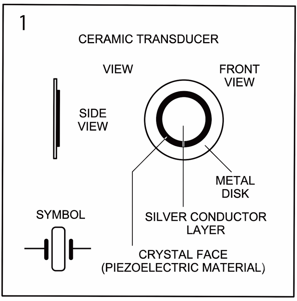
Many crystals are used in the manufacture of electronic components. In the case of quartz crystal, the presence of directional charges allows for a series of special applications in modern electronics. In fact, the ceramic transducer described here is composed of a piezoelectric material. If we deform the crystal, we will generate a voltage, and if we apply a voltage, we will generate deformation (Figure 1). Thus, the orientation of charges is both affected by the action of mechanical forces and produces mechanical forces when under the action of electric fields.
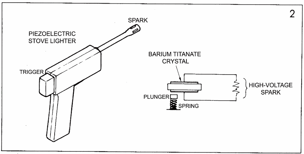
Similar crystals, which exhibit this piezoelectric effect, can produce very high voltages when subjected to mechanical forces. This is the case with barium titanate, used in stove lighters, etc., which can produce hundreds of thousands of volts when subjected to a shock of a certain intensity (Figure 2).
Small ceramic transducers also produce voltages when subjected to mechanical stress, but at a lower power than barium titanate.
Similarly, when an electric field of a certain frequency is applied to their body, they vibrate, producing sound. These transducers are widely used in electronic watches (in models with alarms or music), LCD electronic games, music cards, and other devices.
Regarding their size, transducers come in various sizes, the most common being the size of the spout of a small soda bottle. These transducers are quite thin, no more than a millimeter thick.
In watches, they are fixed (glued) to the back cover. To remove them, you need a blade or sharp knife, taking extreme care not to damage them.
PROJECT 1 - Police Siren
This siren has similar characteristics to those used on French police vehicles.
The schematic diagram of the circuit is shown in Figure 3.
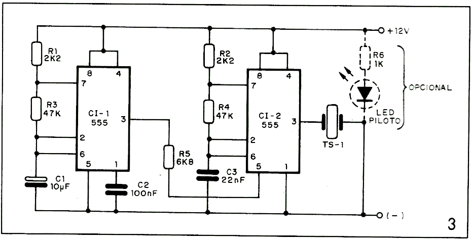
Integrated circuit CI-1 operates at a very low frequency, being responsible for changing sounds. The second integrated circuit is a modulator, operating at a much higher frequency.
Many different effects could be achieved by replacing Cl with another electrolytic capacitor with values between 1 and 47 µF. C3, which is responsible for the siren's tone, can also be replaced with other capacitors with values from 1 to 100nF.
For a completely different effect (a sound similar to that of alarm sirens), simply replace R5 (6.8k) with a 100 µF x 16V electrolytic capacitor. When the first integrated circuit generates a pulse, the electrolytic capacitor will charge and then discharge (and so on), generating a modulation voltage that is applied to pin 5 of the second integrated circuit.
The circuit can be powered by either 6 or 12V from a power supply or even batteries.
In fact, the output power isn't great, as the project is limited to demonstrating how a ceramic transducer works. For greater power, modifications are required, such as replacing TS1 with a speaker or tweeter. Therefore, any modifications to the circuit are recommended only for those with some experience.
ASSEMBLY
Figure 4 highlights the assembly on a printed circuit board.
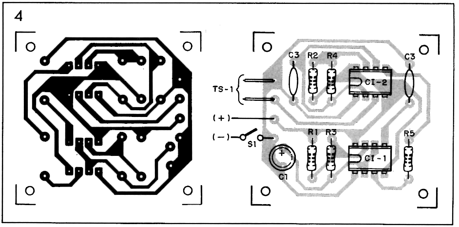
The resistors are all 1/8 or 1/4W. Capacitor C1 is an electrolytic capacitor rated for 16V, while the other capacitors are ceramic and should also have operating voltages of 16V or higher.
It is best to attach the circuits to appropriate 8-pin sockets, as for those less experienced, lengthy soldering could damage them due to excessive heat.
The LED is optional and does not need to be used; its function is to indicate when the circuit is working.
Two wires must be soldered to the TS1 transducer for connection to the PCB. One wire will be soldered to the metal strip and the other to the conductive layer; they should preferably be flexible. Soldering should be done quickly, without leaving excess solder on the component.
It is important to pay attention to the polarity of C1 when soldering it, as well as the position of the integrated circuit terminals, which have a chamfer or a dot at their ends corresponding to pin 1.
The other components do not require much attention; only the values must be correctly observed.
TESTING AND USE
Before connecting the circuit, it's a good idea to check the assembly to ensure everything is set up correctly.
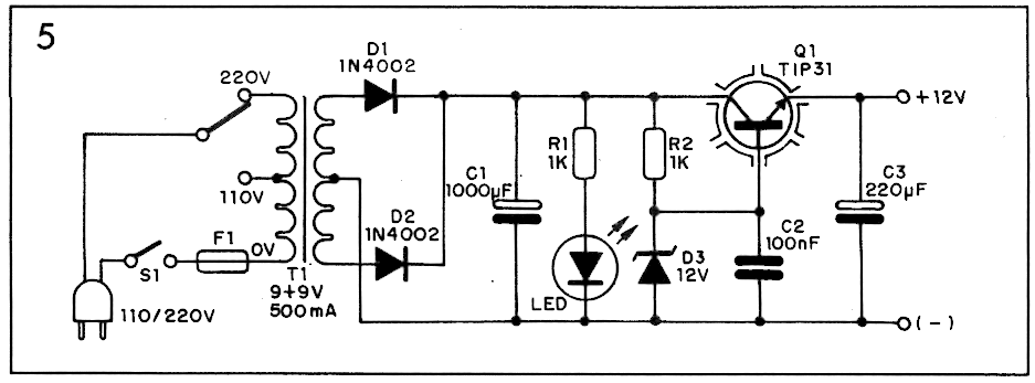
We suggest using a 12V power supply to power the circuit in Figure 5.
Testing the circuit is quite simple; simply connect it to the power supply and it will immediately start working. Applying voltage to the transducer will cause it to vibrate, generating the siren sound.
The circuit can be used in toys or even as an audible alarm for measuring instruments, testers, etc. The circuit's applications are up to individual discretion and taste.
PROJECT 2 - Pressure or Knock Alarm
Our second project is an interesting alarm using the same ceramic transducer used in the siren as a sensor.
As explained previously, if we deform a crystal, we will generate a voltage, and if we apply a voltage, we will generate a deformation. Based on this circuit, we developed an alarm that uses ceramic transducers as sensors.
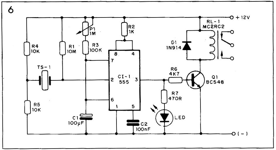
As can be seen in Figure 6, TS1 is connected to a resistive network (voltage divider) and the other end is connected to pin two of IC1 (trigger input).
When TS1 experiences any pressure (or a small impact), it will trigger a trigger pulse on the integrated circuit, activating a relay that, in turn, activates a siren, light, or other intrusion warning device. The trigger time can be adjusted on P1 from 4 to 50 seconds. However, those who require a longer trigger time simply increase the value of electrolytic capacitor C1 (up to 1000gF due to leakage in these higher-capacity components). Resistor R1 prevents loads from activating the system without applying some mechanical force to TS1. The circuit is powered by 12V, and the power supply shown in Figure 6 is compatible with this circuit. For a 6V power supply, for example, you just need to replace the MC2RC2 relay with the MC2RC1 relay, which is for 6 volts. The rest of the assembly does not require any changes.
ASSEMBLY
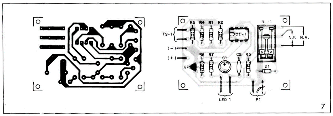
The components are all common and readily available. Resistors can be 1/8 or 1/4 W, and P1 is a 1 MΩ linear potentiometer.
Capacitor C" is electrolytic, and C2 is ceramic. Both should have a working voltage of 16 V or higher. We recommend mounting the integrated circuit in a suitable socket.
The LED can be any type or color, and its function is to signal when the relay is activated. D1 is a general-purpose diode, either 1N914 or 1N4148.
Transistor Q1 can be any general-purpose type, as long as it is NPN.
For TS1, any ceramic transducer can serve as the sensor, and the wires cannot be too long, as this compromises the sensor's stability. An infinite number of sensors can be connected, as they are connected in parallel.
When assembling, it is important to observe the polarity of certain components; if soldered in reverse, they may be damaged. Soldering should be quick and without excess solder.
TESTING AND USE
Testing the circuit is simple: simply connect it to the power supply and apply pressure (mechanical force) or tap lightly on the side of the metal blade of TS1. The relay will immediately activate, and the LED will emit light. The trip time is adjusted using potentiometer P1.
The relay's NC contacts are used to turn off the load and NO contacts to turn it on when the relay is energized. The load can be a lamp, siren, or other warning device.
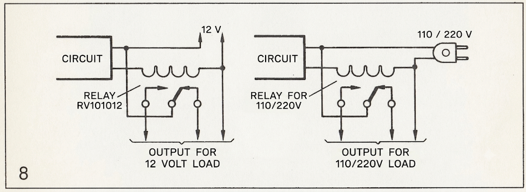
The relay can drive loads of up to 240W at 110V and 480W at 220V. Therefore, to activate a higher-power load, a second relay must be used, depending on the warning system voltage (Figure 8).
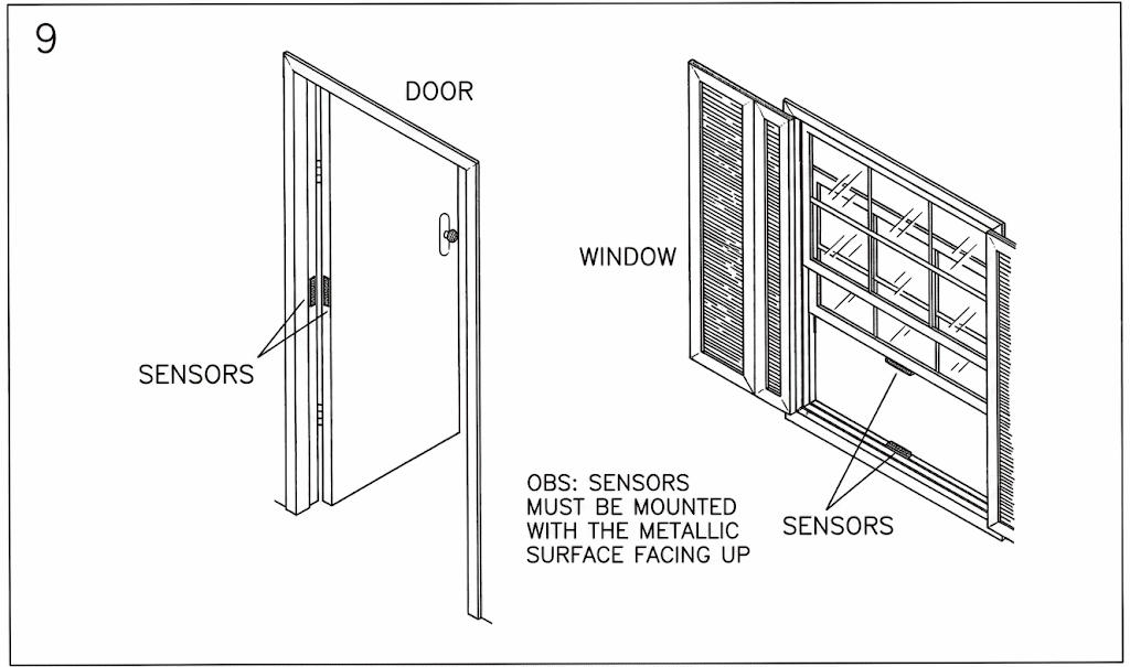
The sensors can be installed to protect an entrance, window, or even medium- or large-sized objects, as shown in Figure 9.
The sensor is triggered when any of the sensors is disturbed by an intruder who steps on or exerts pressure on it in an attempt to pass through an area or passageway. In the case of an object, the sensor is triggered when it is removed from its original location. Upon removal, the sensor will leave the pressure state and return to the normal state. This state change will cause mechanical stress, triggering a pulse that will activate the system.
MATERIAL LIST
Projeto 1
CI1, CI1 – 555 – integrated circuit
R1, R2 – 2k2 – resistors (red, red, red)
R3, R4 – 47k - resistors (yellow, violet, orange)
R5 – 6k8 – resistor (blue, gray, red)
R6 – 1k – resistor (brown, black, red)
Led - common red led
C1 - 10µF x 16V - electrolytic capacitor
C2 – 100nF x 16V – ceramic capacitor
C3 – 22nF x 16V – ceramic capacitor
TS1 - ceramic transducer (see text)
Projeto 2
CI1 – 555 – ceramic capacitor
Q1 – BC548 or equivalent – transistor
D1 - 1N914 or equivalent – diode
Led – common red led
P1 – 1MΩ - linear potentiometer
R1 – 10M – resistor (brown, black, blue)
R2 – 1k – resistor (brown, black, red)
R3 – 100k – resistor (brown, black, yellow)
R4, R5 – 10k – resistors (brown, black, orange)
R6 – 4k7 – resistor (yellow, violet, red)
R7 - 470Ω – resistor (yellow, violet, brown)
C1 - 110µ x 16V - electrolytic capacitor
C2 – 100nF x 16V – ceramic capacitor
RL1 – MC2RC2 (12V) – relay
TS1 - ceramic transducer (see text)
Power supply
Q1 – T1P31 – transistor (with heatsink)
D1, D2 – 1N4002 – diodes
D3 – 1N759 (12V) – zener diode
Led – common red led
R1,R2 – 1k x 1/8W – resistors (brown, black, red)
C1 - 1000µF x 25V – electrolytic capacitor
C2 – 100nF x 16V – ceramic capacitor
C3 - 220µF x 16V - electrolytic capacitor
S1 - 2-position switch
S2 - simple switch
F1 – AI – fuse
T1 - primary transformer with 110/220V and secondary of 9.0.9V x 500mA
Miscellaneous: mounting box, sockets for integrated circuits, fuse holder, knob, printed circuit board, heatsink, pigtail, wire, solder, etc.


