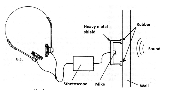
In figure 1 we give an idea of how this device can be used in listening through walls.

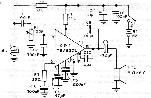
The very simple proposed circuit is shown in figure 2.

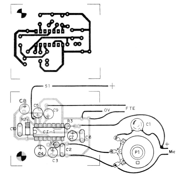
The arrangement of the components on a printed circuit board is shown in figure 3.

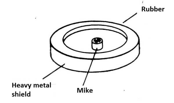
For listening through floors and walls the microphone needs to be equipped with a special acoustic system. This system consists of a heavy metal disc with the padded edges as shown in figure 4.

The disc shall weigh at least 500 grams so that side sounds are damped and only the front sound of the wall or floor are picked up and amplified.
CI-1 - TBA820 - integrated circuit
RESISTORS
P1 - 100 k - potentiometer
R1 - 33 ohm - resistor (orange, orange, black)
R2 - 56 ohm - resistor (green, blue, black)
R3 - 10 k - resistor (brown, black, orange)
CAPACITORS
C1 - 100 nF - ceramic capacitor
C2 - 100 pF - ceramic capacitor
C3. C7 and C8 - 100 uF - electrolytic capacitor
C4 - 47 uF - electrolytic capacitor
C5 - 220 nF - ceramic capacitor
C6 - 100 nF- - ceramic or polyester capacitor
C9 - 470 uF - electrolytic capacitor
C10 - 68 uF - electrolytic capacitor
SEVERAL
MIC - electret microphone
B1 - 6 V - 4 small batteries
F - handset or speaker from 8 to 40 ohms
S1 - Single switch
Printed circuit board, battery holder, mounting box, wires, solder, etc.


