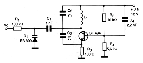
In the figure we show a Varicap-controlled VCO capable of generating signals in the range of a few megahertz up to more than 200 MHz. Although frequency control is achieved when using a varicap like the BNB809, even a common diode like the 1N4002 works as such, but with a smaller range of performance. The coil, C2 and C3 depend on the central frequency generated according to the following table:
Frequency Range L1 C2 C3
1 to 4 MHz 40 turns 100 pF 220 pF
4 to 10 MHz 12 turns 47 pF 100 pF
10 to 50 MHz 8 turns 22 pF 27 pF
50 to 100 MHz 6 turns 10 pF 10 pF
100 to 150 MHz 3 turns 4.7 pF 4.7 pF
The coil is wound with 28 AWG wire in the form of 1 cm without core. We observed that the values in the table are approximate and changes may be necessary depending on the tolerances. The transistor also supports equivalents such as 2N2218 and 2N2222 to obtain a slightly higher power for the signal. This signal can be taken either from the collector of the transistor or from a second coil wound over L1. The number of turns of this coil depends on the desired impedance but in general it will be between half and a quarter of the turns of L1. The capacitors must all be ceramic.