
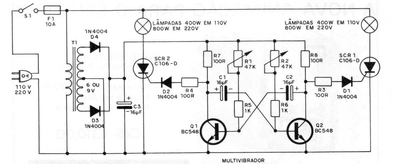
This circuit was obtained in a 1980 publication and was suggested for balls, parties, vehicles entering and leaving, Christmas tree, etc. The complete circuit is shown in the figure. It is an astable multivibrator formed by transistors Q1 and Q2 that alternately trigger two SCRs that can control loads of up to 400 W in each channel in the 110 V network and up to 800 W in the 220 V network. We have two parts to consider in this circuit: the low voltage part whose power comes from a transformer, and the high voltage part connected to the network that supplies the SCRs.
| Clique na imagem para ampliar |


