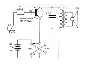
This circuit found in a 1981 documentation consists of a transistor tester of general use and that serves to test both PNP and NPN transistors, just by activating the switch that inverts the polarity of the power supply. The complete circuit of the fitting room is then shown in the figure. As we can see, it is a simple HartIey oscillator that operates on the audio track with the transistor being tested as an active element. If the transistor is in good condition, the oscillator works, in which case the speaker will emit an audible sound as an indication. If the transistor is bad, the oscillator does not work, and no sound is output from the speaker.