
A
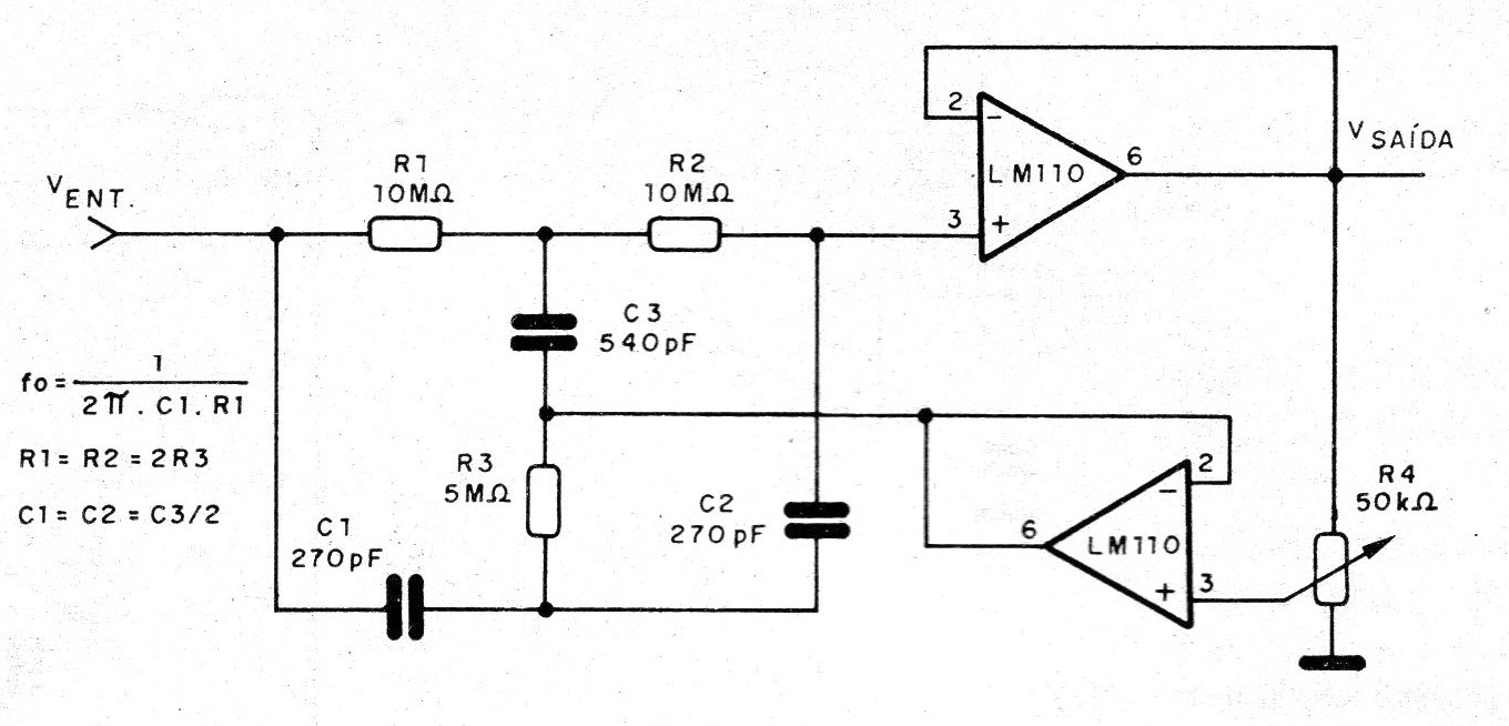
The adjustable Q-factor rejector filter in the figure is based on two LM110. These integrated ones consist of voltage followers that use super-gain transistors to require a very low input bias current, without sacrificing speed. The central frequency depends on R1 and C1 according to the formula placed next to the diagram. Resistors R2 and R3 and capacitors C1 and C2 must maintain relations with R3 and C3 according to expressions also indicated in the diagram. The adjustment of the Q factor is done in the 50k ohms (or 47k ohms) potentiometer. The values given in the circuit are for the frequency of 60 Hz.
| Clique na imagem para ampliar |


