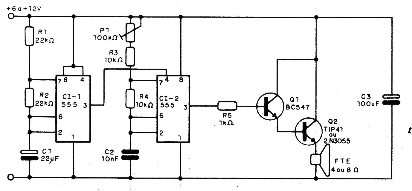
This circuit uses integrated 555 and an amplification step with transistors, as we can see in the diagram. The integrated CI1 works as a very slow astable, which is responsible for the modulation, controlling the operation of the second integrated (C12), which is an astable responsible to produce the audio signal. In the first case, the modulation frequency is fixed, determined by R1, R2 and C1, but nothing prevents a 100k ohms trimpot from being used, in series with a 10k ohms resistor, instead of R1 or R2 and so we can justify this effect. For the second oscillator, which produces the audio tone, we have an adjustment made in P1. Note that the signal produced is a fixed frequency intermittent sound, like a beep, which is different from the sirens described so far, in which we have tonal variations. Modulation, in this case, is done by interrupting the sound. The interrupted modulated audio output is applied to an amplifier stage with two transistors. The first, a BC547, works as a driver, and the second as a power output, directly exciting a good-performance speaker. For the case of 2N3055, which has good power, the load can be 2 ohms, thereby obtaining greater power, especially in the case of 12 V power. Both the TIP42 and 2N3055 must be mounted on a good heat radiator. The resistors are all 1/8 or 1/4 W, and the electrolytic capacitors must have a working voltage according to the supply. C2 can be changed in the range of 10 nF, up to 47 nF, if it is necessary to generate more serious sounds.