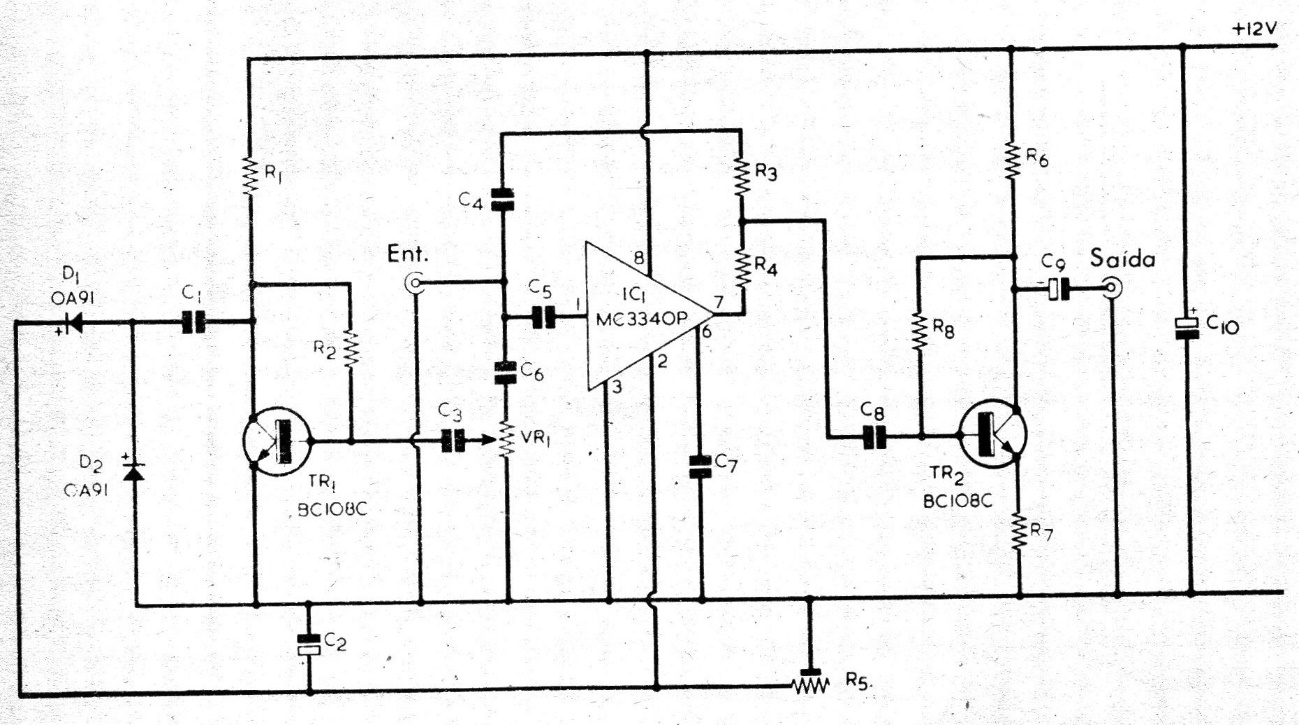
This circuit is from the 70's by A. Fanzeres. We kept the original text. It has already been said that on audio it is possible to write hundreds of articles daily and never exhaust the subject. It is impressive how every day the most varied circuits appear, for the most diverse audio functions, aiming at the great majority of them to obtain perfect fidelity. Despite the high quality of current recordings, there is always a certain background noise in them. The circuit we present is simple, but very effective. It works by increasing the attenuation of high frequencies when the audio levels are reduced. It must be located between the output of the recording head and the input of the amplifier. To adjust the limiter, an unrecorded tape is placed in the recorder, VR1 is set at a minimum, the amplifier's treble, and bass controls at maximum, and R5 is set to eliminate the noise produced by the unrecorded tape. The VR1 potentiometer adjusts the action level of the limiter, being made by attempts until obtaining the best point.
LIST OF MATERIALS
R1 = 3.3K
R2 = 560K
R3 = 10K
R4 = 10K
R5 = 47K
R6 = 4.7K
R7 = 2.2k
R8 = 2.2 M
VR1 = 47K
C1 = 0.47 uF
C2 = 1 uF, .16 v
C3 = 0 1 uF
C4 = 1 uF
C5 = 0.001 uF polystyrene
C6 = 0.22 uF
C7 = 470 pF
C8 = 0.22 uF
C9 = 10 uF 16 v
C10 = 100 uF, 16 v.
IC1 = MC3340P
TR1 = BC 108C
TR2 = BC 108 C
TR3. = BFY 50
D1 = OA91
D2 = OA91