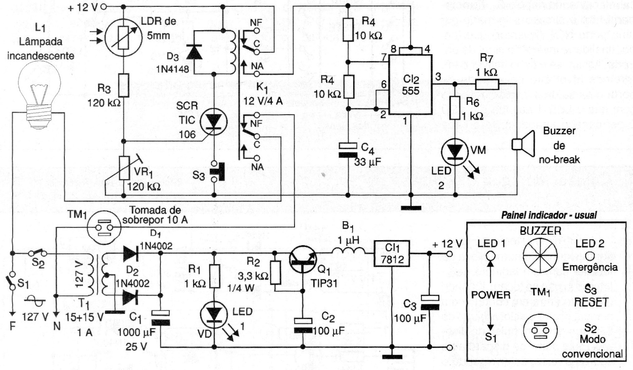
It is an ideal circuit for troubleshooting a bench, in addition to testing devices after repair, with the advantage of not requiring technical monitoring. This is because if a defect occurs during the test, the circuit trips with the relay deactivating the load thus protecting the device, with a visual indication of the defect. To adjust VR1, just connect a dimmer to the TM1 socket and activate S1, then adjust the dimmer so that L1 is bright between minimum and medium. Then the LDR is fixed next to the lamp, adjusting VR1 so that the relay activates. The power of L1 should be 2 to 3 times that of the device under test. This guarantees approximately 70% of the mains voltage to the switched source of the device, which is reasonable for a function test.