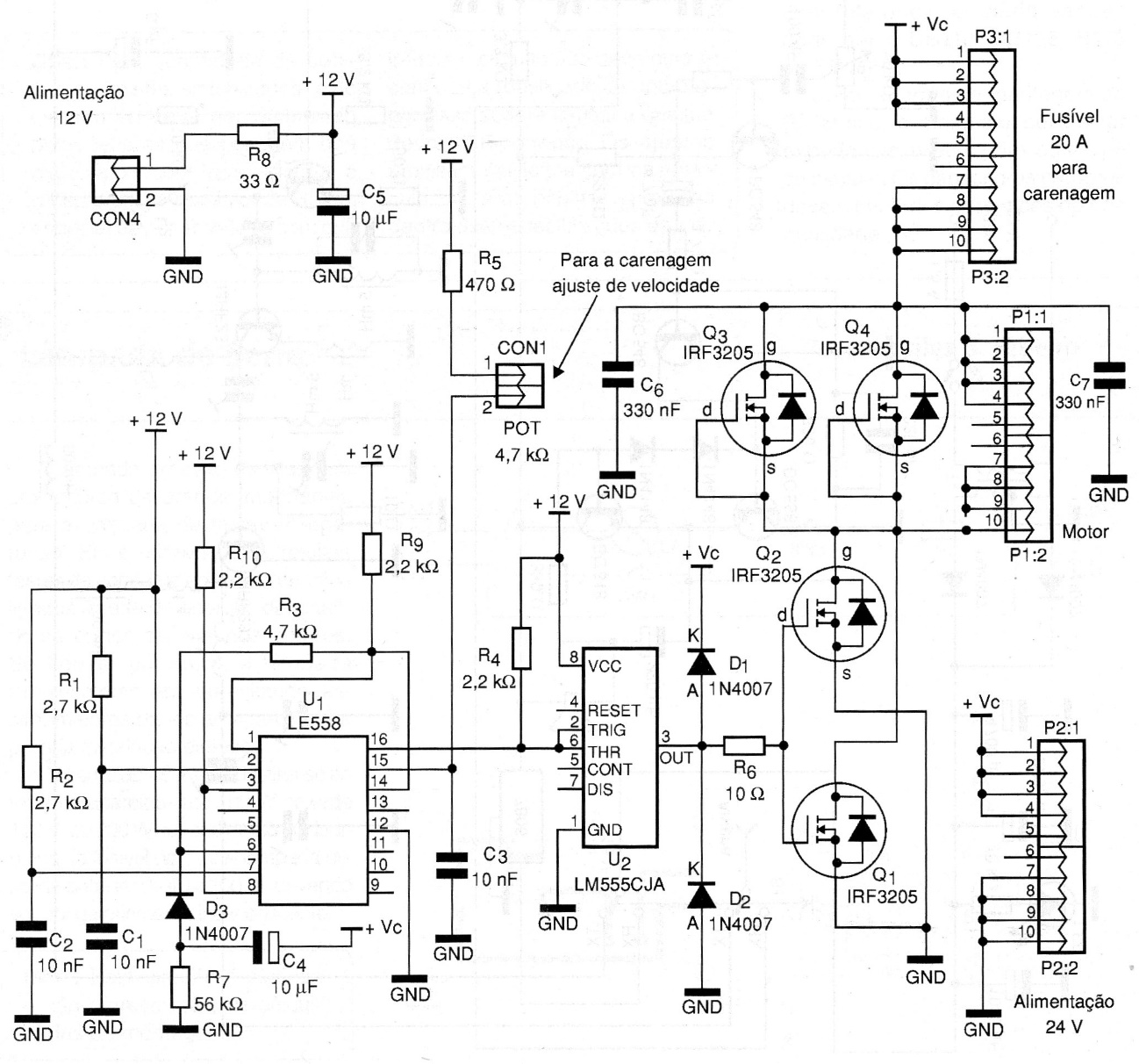
The circuit presented in a 2009 documentation is simple based on the NE558 and NE555 ICs with IRF3205 transistors. The transistors are in the Darlington configuration for greater current capacity. The motor used was a 24 V x 15 A wheelchair, a rather large motor that in this case had a high consumption. Heatsinks were then used in the transistors. The P3 connector goes straight to a 20 A fuse connected to the fairing, but nothing prevents the assembler from adapting the printed circuit board. Remember that the connection paths of the transistors responsible for high currents must be very wide. In the following figures we have the control diagram and the drawings of the printed circuit boards. The circuit can be used as a shield for microcontrollers with minor adaptations.


