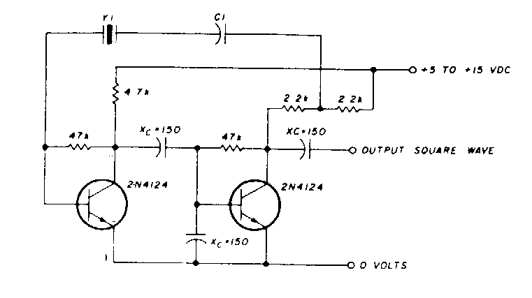
This circuit is from a 60's documentation. The capacitance C1 can be between 20 pF and 0.01 uF depending on the generated frequency. Equivalent transistors may be employed.
| Clique na imagem para ampliar |

This circuit is from a 60's documentation. The capacitance C1 can be between 20 pF and 0.01 uF depending on the generated frequency. Equivalent transistors may be employed.


