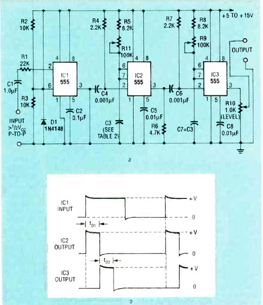
Found in a September 1992 Radio Electronics magazine article, this circuit generates a pulse as shown in the graph below the diagram. The timings can be changed by swapping C3 and C7.
| Clique na imagem para ampliar |

Found in a September 1992 Radio Electronics magazine article, this circuit generates a pulse as shown in the graph below the diagram. The timings can be changed by swapping C3 and C7.


