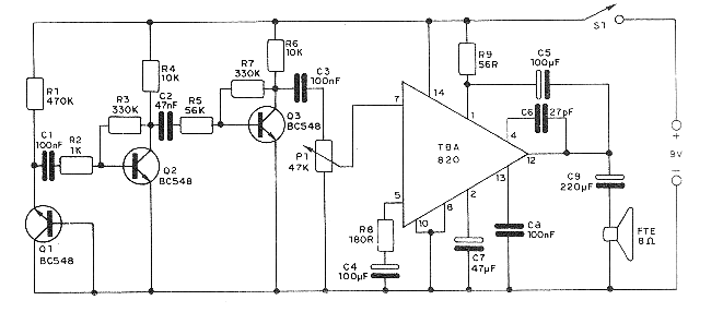
Note: In the original version of this project, the audio amplifier was incorporated into the printed circuit board, although a version was also provided to be connected to an external amplifier. This second version is the most recommended for a current assembly, since its components are easily obtained. For the board version, the audio amplifier integrated circuit is not so easy to obtain, so some readers who try it may have difficulty obtaining it. Even in the board version, we suggest that the audio amplifier sector be left out and the circuit be connected to an external amplifier.
Many people have trouble sleeping, whether due to insomnia, noisy neighbors or living in a place where constant street noise is disturbing. If you need something to help you sleep, preventing the noises of the neighborhood from bothering you, an electronic solution is possible and that is exactly what we will describe in this article. Easy to assemble, it uses few low-cost components. The basic idea is what we call white noise.
White noise, similar to that of wind, rain, waterfall water, or when you place a seashell near your ear, has very interesting therapeutic properties. Since this noise is composed of a wide spectrum of random frequencies, our brain cannot focus on it, and therefore relaxation occurs. This occurs because noises with a defined pattern, such as music, the sound of a hammer or a conversation, have a defined pattern and therefore the brain focuses on it and we are unable to relax. This is why people can sleep more easily when they are on a beach listening to the sound of the sea, near a waterfall or even with the wind or rain, which are natural sources of white noise.
Another important characteristic of white noise is the fact that it can cover up other noises if their intensity is high. For example, in a noisy place, a source of white noise of greater intensity can cover up the noise and thus help with relaxation. Therefore, a source of white noise placed near a person in a noisy place can serve as a powerful aid to relaxation and induce sleep easily.
There are several ways to obtain white noise, and some have even been explored in the form of CDs with recordings of the sound of the sea or rain that are played next to the person who wants to relax or sleep. Some CDs even include additional relaxing sounds of frequencies that have been shown to have positive effects on people, such as the rhythmic ringing of a small bell, a resource that is even used in monasteries to induce monks into a state of relaxation or complete trance.
In our case, what we will assemble will be a simple and completely harmless white noise generator that has the great advantage of not acting harmfully on the body, as occurs with chemical products such as pills and drinks, especially when used without medical supervision.
If you need a good night's rest or have a neighbor who usually uses their stereo at a higher volume than normal, the setup we have described may help. In any case, if your problem is more serious, you should also consult a doctor, who may be able to help you with additional therapeutic solutions.
As a noise suppressor, what happens is that if the average intensity of the white noise is greater than that of the disturbing sound, the disturbing sound is “blocked out” and cannot be heard. This is when the relaxing properties of white noise come into play.
How it Works
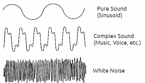
The sleep inducer we describe is based on a white noise generator, a circuit that produces a sound similar to that of rain, wind or waterfall. It is a hiss that in reality contains all possible audible frequencies, produced randomly. White noise is defined precisely in this way: a random distribution of all frequencies in the spectrum, according to a pattern shown in figure 1.
To generate this type of noise electronically, we take advantage of the thermal characteristics of a transistor. At a temperature higher than absolute zero, the atoms of all materials vibrate with an intensity that depends on several factors. In a semiconductor material, such as that used in the manufacture of diodes and transistors, the natural vibration of the atoms releases charge carriers at the junctions. These carriers then generate currents of random intensity and frequency, which can be amplified, resulting in white noise.
We can hear these signals in amplifiers and common radios when, without sound, we turn up the volume and hear the background hiss. This is the white noise generated by the circuits themselves under the conditions indicated. In some cases, excess noise is a problem that must be eliminated from devices that work with sounds.
In the sleep inducer described, we connect the transistor in an unconventional way, as shown in figure 2, so that the thermal noise generated at its junction can be taken to an external circuit, where it will be amplified by two other transistors.
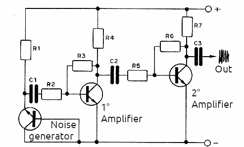
Since the signal generated by the transistor junction is very weak, it is applied to the base of a first amplifier and from the collector of this transistor to the base of a second amplifier. In the original project, we used a TBA820 integrated circuit as the final power amplifier. This IC is not very easy to obtain, so there are two possibilities for a more modern version of the project. One of them is to use a more modern IC such as the LM386 or even TDA2002 (more powerful). The other possibility is to use an external audio amplifier.
A alimentação do circuito pode ser feita com pilhas (6 pilhas comuns, se o amplificador também for usado ou fonte) ou ainda uma bateria de 9 V, se apenas o circuito gerador de ruído for montado, caso em que será utilizado o amplificador externo. A fonte, se for usada, deve ser de acordo com o amplificador e ter excelente filtragem, para que não ocorram roncos (diferentes do ruído – os roncos são gerados na frequência de 60 Hz ou 120 Hz da rede).
Material
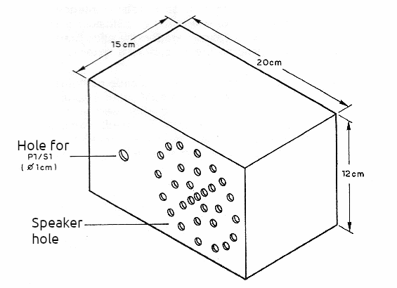
The basic materials for this project are easily obtainable. We suggest that the set be installed in a box, as shown in Figure 3. The box can be made of metal, wood or plastic. If the amplifier is included, holes should be made on the front of this box to allow sound from the internal speaker to come out. The other hole is for attaching the potentiometer that serves as a volume control. This potentiometer will contain the switch that turns the device on and off.
For the version without the amplifier, there will only be one hole for the potentiometer and a hole at the back for the output of a cable that will connect the device to the external amplifier. This cable must be shielded to prevent humming.
The electronic components are not difficult to obtain. The transistors can be BC548 or equivalent general-purpose transistors. The integrated circuit is more critical, but as explained, other configurations or an external circuit can be used. The resistors are 1/8 W, with the indicated values being common.
There are two types of capacitors in this assembly. Those smaller than 1 uF can be ceramic or polyester, while larger ones can be electrolytic with a working voltage of at least 12 V. Potentiometer P1 serves as a volume control, and can be 1 M with or without a switch. If it is without a switch, an additional switch must be used to turn the device on and off.
The speaker is a 10 cm or larger unit with 8 ohms of impedance, or according to the output of the amplifier IC, if another is used. As additional components, we have the battery holder or the power supply material that includes a 7.5 + 7.5 V or 9 +9 V transformer with 200 to 300 mA, a 1000 uF x 16 V electrolytic capacitor and two 1N4002 diodes or equivalent. The finish of the device will depend on the skill of each assembler.
Assembly
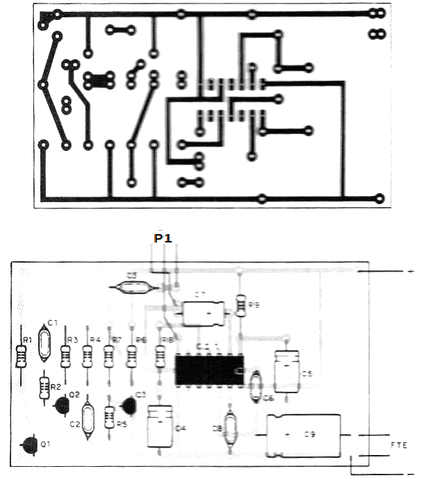
The complete version must be assembled on a printed circuit board, since we are working with an integrated circuit. However, for the simplified version, with the use of an external amplifier, it is possible to assemble it on a terminal bridge. We will give both options.
So, we will start by showing in Figure 4 the complete generator circuit, in the version that includes the original amplifier. In the version without the amplifier, the signal will be taken from the P1 cursor and all the components to the right of it in this diagram will be unnecessary.
The printed circuit board suggested for this assembly is shown in Figure 5.
The following precautions must be taken when assembling:
a) When soldering the integrated circuit, observe its position and ensure that no solder spreads occur that could short-circuit the terminals.
b) Electrolytic capacitors are polarized components. Observe their polarity.
c) Observe the position of transistors, as they are also polarized components.
d) Take care when placing resistors in the circuit, as their values are given by the colored bands.
e) Be careful when connecting the transformer, noting that some types have two voltages (110 V and 220 V) and the appropriate wires must be chosen according to their network.
f) The power supply diodes have a specific connection position. If they are reversed, the device will not work.
g) When assembling the power supply, switch S1 can be connected to the potentiometer or separate. In the case of this power supply, it is connected before the transformer.
In figure 6 we show a bridge version in which we do not have the amplifier circuit.
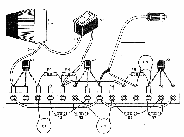
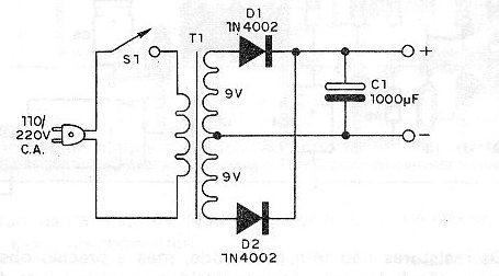
Note the connection of the shielded wire to the input plug for the amplifier. In this case, an RCA plug was illustrated, but see if your amplifier uses a different type. Figure 7 shows the power supply diagram, for a version with a built-in amplifier.
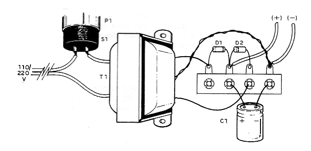
The appearance of the power supply assembly based on a terminal strip is shown in Figure 8. Note the polarity of the diodes and the electrolytic capacitor and the position of the main switch.
Testing and Use
Check all connections, especially the positions of polarized components. Check if the solders are correct and free of dispersion. After that, place the batteries in the holder or turn on the power supply. Activate switch S1 using the potentiometer (if it is paired) and open the volume. If an external amplifier is used, turn on the amplifier and open its volume with the plug connected to the corresponding input (AUX or MIC).
A sound similar to wind or rain should be produced. If there is a humming sound in the emission, check the connections to the amplifier, especially the grounding mesh of the shielded cable. If your version uses a power supply, invert the plug in the socket (turn it half a turn). If no hissing sound is emitted, place your finger on terminal 7 of the integrated circuit (if that is your version). There should be a humming sound. If this does not occur, the problem is with the IC. If an amplifier is used and there is no hum, check the connection to the amplifier or whether the selector switch is set to MIC or AUX.
To use, simply turn on the device and adjust the volume so that it is pleasant to listen to, producing relaxation or even blocking out ambient noise. In the mains-powered version, consumption is low, which means that the device can be left on for long periods of time. In the version with an amplifier, even using a battery, consumption is also low and its durability will be long.
Material List
CI – 1 – TBA 820 - Amplifier integrated circuit
Q1, Q2, Q3 – BC548 or equivalent - transistors
P1 – 47k - potentiometer with switch (S1)
R1 – 470k x 1/8W - yellow, violet, yellow resistor
R2 – 1k x 1/8W - resistor (brown, black, red)
R3, R7 – 330k x 1/8 - resistor (orange, orange, yellow)
R4, R6 – 10k x 1/8W - resistor (brown, black, orange)
R5 – 56k x 1/8W - resistor (green, blue, orange)
R8 – 180R x 1/8W - resistor (brown, gray, brown)
R9 – 56R x 1/8W - resistor (green, blue, black)
C1 – 100nF - ceramic or polyester capacitor
C2 – 47nF - ceramic or polyester capacitor
C3 – 100 nF - ceramic or polyester capacitor
C4, C5 – 100 µF x 12V
C6 – 27pF - ceramic capacitor
C7 – 47 µF x 12V - electrolytic capacitor
C8 – 100 nF - ceramic or polyester capacitor
C9 – 220 µF x 12V - electrolytic capacitor
Miscellaneous: 8 Ohm speaker, power supply, printed circuit board, battery holder, potentiometer knob, mounting box, etc.

