

Figure 1 – Circuit of the LED indicator
Which LED is turned on depends on the direction of the current flowing across the circuit. You can use a green LED to indicate forward and a yellow LED to indicate reverse. The value of resistor R depends on the voltage used to power the circuit, according to the following table:
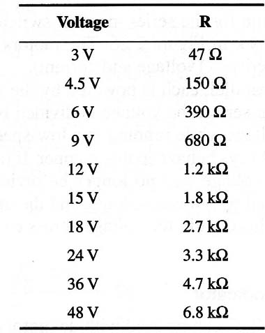
If the motor operates in a range of voltages via the use of a speed control, use the appropriate resistor for the highest applied voltage. All the resistors are 1/4 W x 20%.
Note: this circuit can be used in other applications where the direction of a DC current must be monitored.


