The circuit we present makes use of an H-bridge in an anti-phase control in order to obtain changes in the speed of a two-way motor.
With the transistors used the maximum recommended current is of the order of 1 A, but higher current capacity transistors can be used.
The base of the circuit is an oscillator with the active duty cycle drawn up around one of the doors of a 4093.
The other three ports are used to apply opposite phase signals to the H-bridge which controls the motor.
One drawback of this circuit is that at the 50% active duty cycle, which corresponds to the motor stopped, the motor remains consuming power and depending on the application it can oscillate.
In Figure 1 we have the complete diagram of the speed control PWM with rotation inversion.

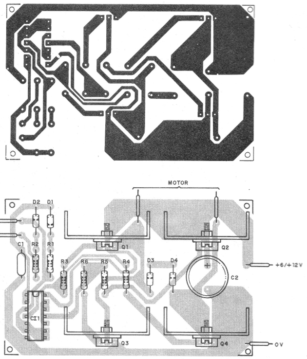
The printed circuit board for the assembly is shown in Figure 2.

Transistors must be fitted with heat sinks and their position, as well as the integrated circuit, must be observed.
The resistors are 1/8 W with any tolerance and the capacitor C1 must have its value chosen according to the motor, so that it does not vibrate too much.
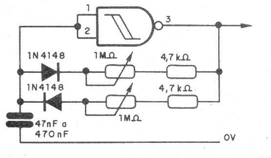
For a better control, a double potentiometer can be used, so that when one section has increased resistance the other has decreased it, according to the connection shown in Figure 3.

Q1 to Q4 - TIP120 - NPN power Darlington transistors
CI-1 - 4093 - integrated circuit
D1, D2 - 1N4148 - general purpose diodes
D3, D4 - 1N4004 - silicon rectifier diodes
R1 - 22 k ohm - resistor - red, red, orange
R2 - 2k2 ohm - resistor - red, red, red
R3 to R6 - 10 k ohms - resistors - brown, black, orange
P1 - 100 k ohm - potentiometer
C1 -1 - 220 nF - polyester or ceramic capacitor - see text
C2 - 1000 uF - 16 V - electrolytic capacitor
Miscellaneous:
Printed circuit board, heat sinks, power source or battery, wires, welding, etc.


