
Description:
This package contains a walking-ring synchronous counter. Six Johnson Counter stages are used to perform the functions found in this circuit. The device can be programmed to divide an input by 2 through 10. The output is a square wave for even divisions and nearly a square wave for odd divisions.
Functional Diagram and/or Package:
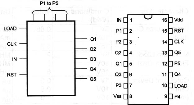
Pin Names:
Vdd - Positive Supply Voltage [3V to 15V]
Vss - Ground
P1 to P5 - Parallel Load Inputs
Q1 to D5 - Dutputs
CLK or DATA - Clock [signal input]
RST - Reset
LDAD - Load Input also called Preset Enable
IN – Feedback lnput
Timing Diagram:
The operation of this device is better understood if the timing diagram is given replacing the truth table. The timing diagram is shown in Figure 1.

Operation Mode
The program is made by changing the feedback according to the table below:
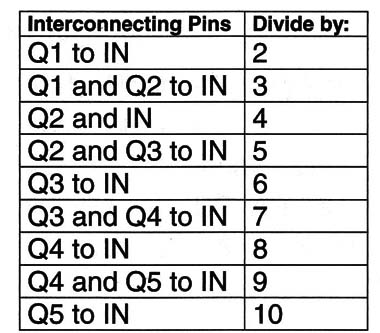
In normal operation Reset and Load are put to the ground. The counter
advances one count for each positive transition of the clock. The outputs QO to Q5 are buffered.
Reset - To reset the circuit, place the Reset input to the “’1 ” logic level.
Load - Parallel load is created by mak- ing the Load input positive.
Electrical Characteristics:

Applications:
Programmable Dividers [2 to 10]
Sine Wave Generators
Frequency Dividers
Timers
Programmable Decade Counters and Greater
Observations:
- The parallel code is specialized.


