
Note: Article published in Eletrônica Total Issue 129 - Brazil, 2008. ART3981S ART5450
Many of our readers have probably noticed the flytraps found in butcher shops and other establishments that tend to attract these insects.
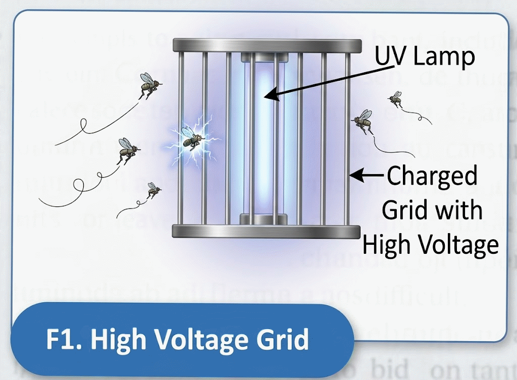
A high-voltage grid surrounds an ultraviolet or blue light bulb, which attracts the insects. When they try to pass through the grid, a high-voltage discharge instantly kills them, as shown in Figure 1.
We can use the same principle to eliminate other types of insects, such as cockroaches. Of course, due care must be taken with the circuit to ensure it does not shock people, so we suggest carefully following the recommended protective measures.
How It Works
The idea is a grid of wires, through which the cockroaches must pass, which is under a high, pulsating voltage of over 3,000 volts. The passage of the insect, even without contact, causes its body to act as a bridge, producing a spark, as shown in Figure 2.
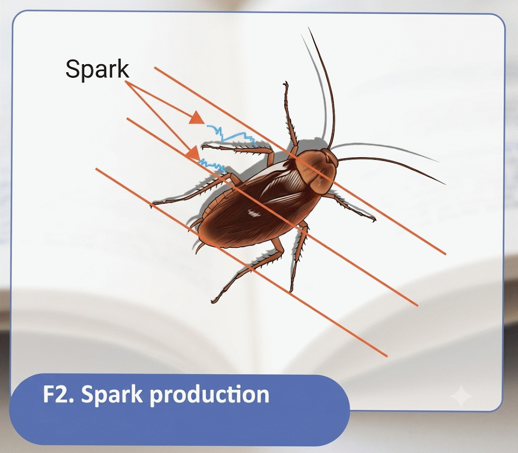
This high-voltage spark is enough to kill the insect. The circuit that generates this high voltage is based on a relatively new component that we have already described in other articles in this magazine: the SIDAC.
SIDAC stands for Silicon Diode for Alternating Current. It is a component with the symbol and characteristic curve shown in Figure 3.
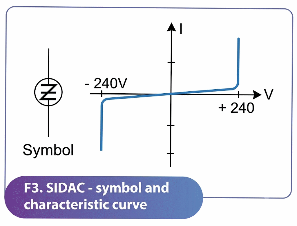
As we can see, the SIDAC is a "solid-state" version of the familiar neon lamp, which triggers by conducting intense current when the applied voltage reaches a certain value.
The advantage of the SIDAC over the neon lamp is that it can conduct very intense currents. In our case, we will use a SIDAC that triggers at a voltage of 240 V.
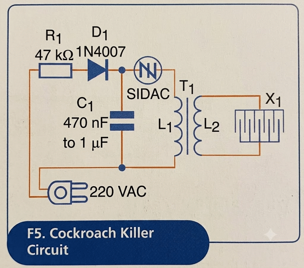
What we then create is a relaxation oscillator circuit; see Figure 4, in which a capacitor charges through resistor R and the diode. When the capacitor reaches a voltage of 240 V, which is less than the peak of the 220 V network (which reaches close to 320 V), the SIDAC triggers, and thus, we have the capacitor discharge through L1.
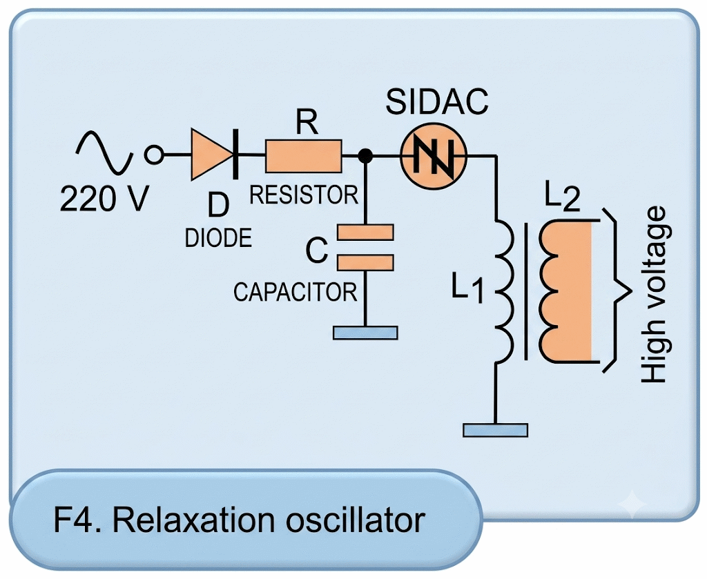
L1 is the primary winding of a high-voltage transformer. The result is the induction of a high-voltage pulse in the secondary (L2), which will be between 2000 and 4000 V. This pulse will electrocute an insect if it is passing through the X-wire network at that moment.
Once the capacitor discharges, the SIDAC turns off, giving the capacitor time to recharge and produce a new pulse. With the values of the components used in the circuit, we will produce several pulses per second, giving the insect no time to escape.
The discharge the insect receives also depends on the charge stored in the capacitor. With larger capacitors, the circuit will be more efficient.
An important feature of this circuit is its low consumption, since the capacitor's charging current is very small. The circuit consumes less than 10 W of power, which certainly will not weigh down the reader's bill, even if they leave it on all night.
Assembly
Figure 5 shows the complete diagram of the Electronic Cockroach Killer with SIDAC.
The circuit assembly based on a printed circuit board is shown in Figure 6.
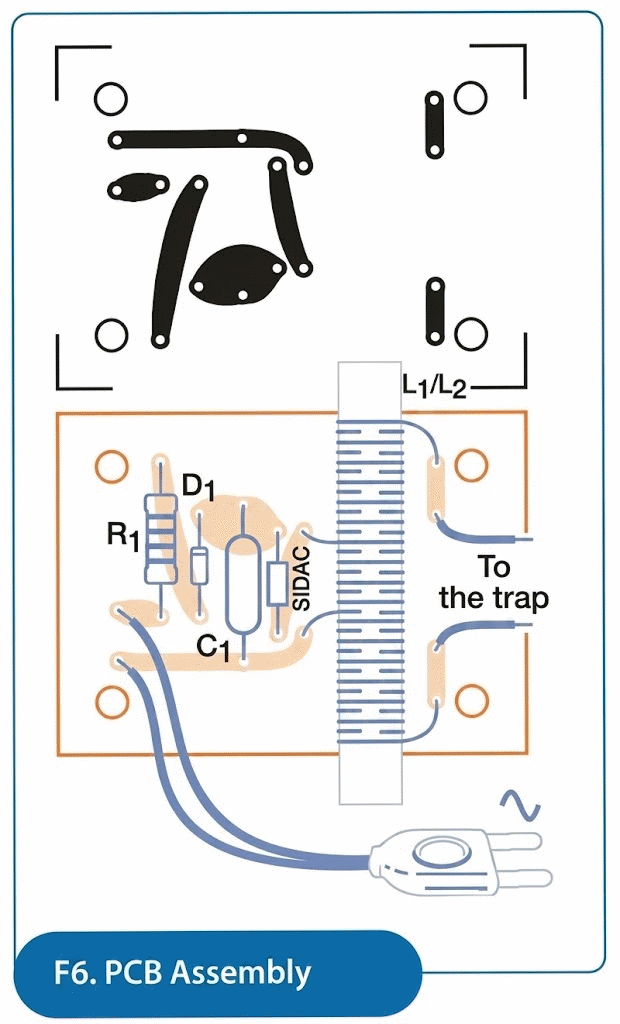
Since few components are used, even a terminal bridge can serve as a base for assembly.
The SIDAC used is from ON Semiconductor, rated at 240 V for the 220 V network. For the 110 V network, a 120 V SIDAC should be used, although this is more difficult to find.
Capacitor C1 must be a high-voltage polyester capacitor for alternating current with an insulation voltage of at least 350 V. This value will determine the intensity of the high-voltage pulses. The reader may even experience higher values than indicated (depending on the size of the cockroaches in your area!), reaching 4.7 µF.
The wire resistor must have a dissipation of at least 10 W, as it will run slightly hot. The transformer is wound by the reader itself on a ferrite rod, 20 cm long or longer, as shown in Figure 7. The diameter can be between 0.8 and 1.2 cm.
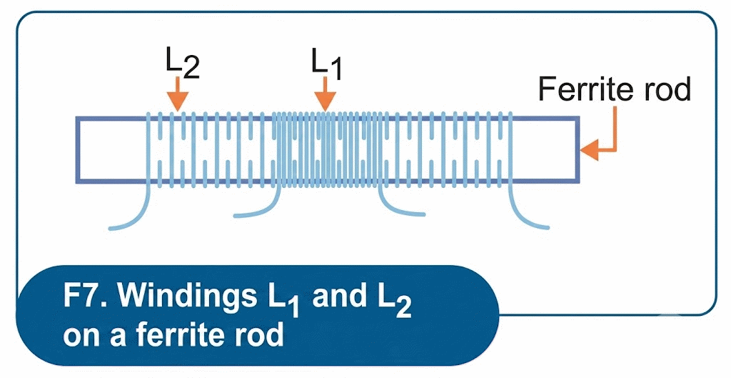
Initially, wrap L2 with 150 to 250 turns of 28 AWG enameled wire or even regular thin-stranded wire (24 or 26). Then, wrap 12 to 15 turns of regular wire around L2 to form L1.
The X1 trap is mounted on a wooden platform with standard nails (see Figure 8).
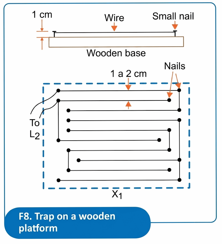
Use thin wire or even stripped copper wire to make the net for the insects to touch.
The circuit should be enclosed in a plastic box because it is powered directly by the power grid. The output to the trap should be made with shielded wire.
Even though the trap can cause unpleasant shocks if accidentally touched, it is isolated from the power grid by the transformer formed by L1 and L2 (T1). Therefore, it should not be placed where pets or people can touch the stripped wires.
Test and Use
When the circuit is connected to the power grid, it should start working immediately. A standard neon light lamp placed against the trap wires will light up, as shown in Figure 9.
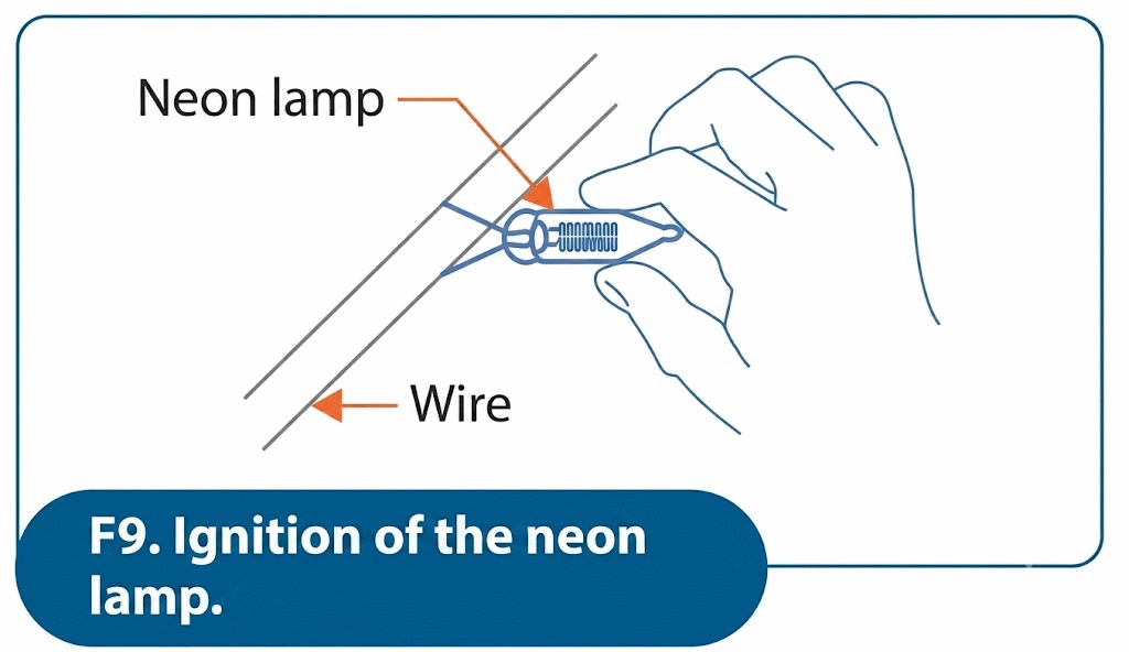
A fluorescent light lamp will also flicker if connected to the wires leading to the trap. If this does not happen, check that the transformer windings (L1 and L2) are not shorted. The wire used must be in good condition and perfectly insulated. Sparks from the transformer indicate a problem with the wire.
If sparks occur in the trap, increase the distance between the wires or remove turns from L2, or increase the turns from L1.
Once the trap is working properly, place "bait" in the trap, such as a sweet substance that attracts cockroaches, and leave the device on.
Materials list
Semiconductors
SIDAC – SIDAC of 240 V – On semi-conductor
D1 – 1N4007 - silicon diode
Resistor
R1 – 47 kΩ 10 W
Capacitors
C1 – 470 nF to 1µF x 350 V - polyester capacitor
Miscellaneous:
T1 – (L1/L2) – transformer – see text
X1 – Trap – see text
Printed circuit board, power cable, ferrite rod, enameled wire or thin common wire, mounting box, bare wire or wire, wooden base, nails, etc.


