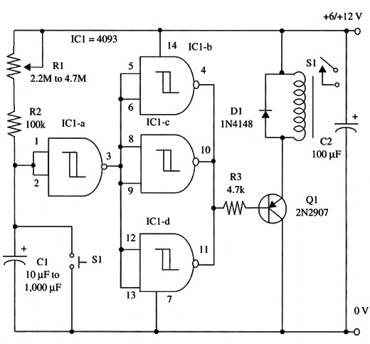
Capacitor C1 is chosen according the intended application. Short time delays can be obtained with low values, in the range between 10 and 100 µF. Large values (e.g., a 1,000 µF capacitor and a 4.7 M ohm potentiometer) can give time delays as high as 45 minutes.
Current drain in the load is fixed by the relay contacts rates. With a 1 A relay, you can control loads up to 100 W. If you want to control more powerful loads, a heavy-duty relay must be used.
The relay coil can be rated for 6 or 12 V. The recommended transistor can sink currents up to 100 mA, and this determines the coil characteristics.
A schematic diagram of the Turn-Off Timer is shown in Fig. 1.

Proper positioning of the polarized components (diode, electrolytic capacitors, and transistor) must be observed.
Connections to external loads are made as shown in ART119E. To drive heavy-duty relays. you should replace Q1 with a TIP31 and reduce R3 to 2.2 k ohm.
Relays up to 500 mA coils can be driven with this new configuration.
IC1 - 4093B CMOS integrated circuit
Q1 - 2N2222 NPN general purpose silicon transistor
D1 - 1N4148 general purpose silicon diode
K1 - 6 or 12 V relay (12 V, 43 mA, 280 9; Radio Shack 275-249 is a suitable unit)
S1 - SPST momentary switch
R1 - 2,200,000 ohm or 4,700,000 ohm potentiometer
R2 - 100,000 ohm, 1/4 W, 5% resistor
R3 - 4,700 ohm, 1/4 W, 5% resistor
C1 - 10 µF to 1,000 µF, 12 WVDC electrolytic capacitor
C2 - 100 µF, 16 WVDC electrolytic capacitor


