
ART631S ART146
The plates of a lead-acid accumulator sulfate when it is left unused for a long time and therefore undergoes a complete discharge. Under these conditions, the accumulator no longer accepts a charge, and even if a small amount is charged, it will be lost in a short time. The most common process for recovering an accumulator that has reached this point consists of performing rapid charges and discharges over a period, so that the sulfation process is reversed and the plates return to normal operating conditions.
However, controlled charging and discharging cycles must be done carefully, as an excess of current can cause an even bigger problem that will completely render the battery or accumulator unusable: the plates deform or even crack. With the device described in this article, fast charging and discharging cycles can be performed in a controlled and automatic way, thus allowing the recovery of 12V batteries of the type used in cars or motorcycles. Small changes to the circuit can make it work with batteries of other voltages.
Features:
* Input voltage: 110/220 VAC
* Output voltage: 13 to 15 VDC
* Charging current: 5 A peaks
* Discharging current: 0.5 A
* Cycle duration: 1/60 second
HOW IT WORKS
Our circuit consists of a power supply with a single secondary winding transformer with a voltage of 21 Vrms. The secondary voltage of this transformer is rectified, obtaining pulses of approximately 35 V peak, which are then applied to a regulator stage with two power transistors in a Darlington configuration. The reference voltage for this circuit is given by a divider formed by resistor R1 and a 15 to 16 V zener diode, which will determine the maximum voltage on the battery during recovery.
P1 determines the setting that will fix the current in the battery being recovered, which is monitored by ammeter A. The battery is connected to the circuit to be charged, but it only receives the positive half-cycles rectified by D1, so we have the application of short-duration pulses with peaks that reach 5 A at the maximum setting, as illustrated in Figure 1.
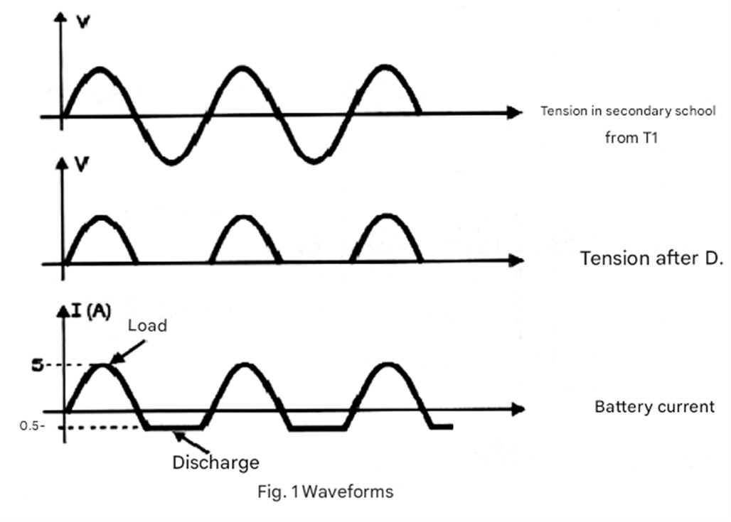
Between the half-cycles applied to the load, the battery discharges through resistor R3, which, depending on its value, determines the discharge current. Values between 22 and 27 ohms can be used, fixing the current at around 500 mA. The recovery time of a battery depends on its condition and can range from a few hours to a few days.
ASSEMBLY
Figure 2 shows the complete diagram of the device.
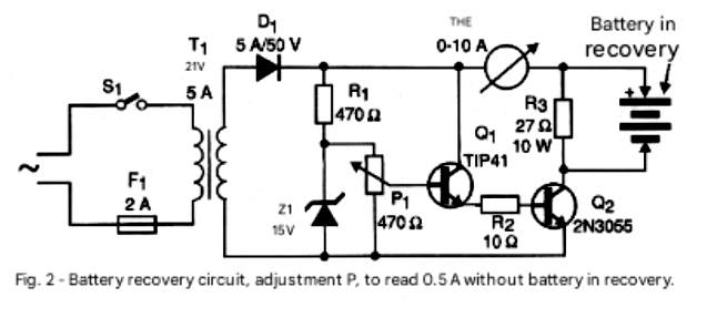
Figure 3 shows the layout of the components on a printed circuit board. However, since few components are used, there is nothing preventing the use of alternative mounting techniques, such as "hanging" them on a terminal strip.
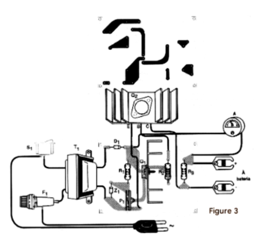
Obviously, given the intensities of the main currents, the use of thick wires in the connections is an important factor. Resistors R2 and R3 should be wire-wound with at least 5 W dissipation, while Z1 is a 1 W zener diode with approximately 15 V voltage (two 400 mW and 7.5 V zener diodes can be connected in series).
Resistor R1 is 1/2W and the two transistors should be fitted with appropriate heat sinks. Diode D1 is 5 A with 50V or more, and the potentiometer is a common carbon potentiometer. For lower cost, the ammeter can be a movable iron type, which, although less precise, is perfectly adequate for the application in question. The transformer should have a primary winding according to the local mains voltage, and for connecting the battery being recovered, we suggest using polarized cables with alligator clips at the ends that will be fixed to the output screw bridge.
TESTING AND USE
When the device is switched on and P1 is adjusted, the instrument should indicate a 500 mA current due to the presence of R3. With a discharged battery connected to the output, the current should rise, reaching peaks of 5 A.
It is not possible to accurately measure these current peaks with a multimeter, as it does not indicate peak values. Ideally, an oscilloscope should be used. The value indicated by the ammeter is an average. The output voltage should reach a maximum of 13 to 15 V measured with the multimeter without a load, or slightly more.
Once the presence of voltage at the output is verified, simply connect the sulfated battery and leave the equipment in operation for periods of 6 to 24 hours. After that, place the battery in a normal charger to check if recovery has occurred.
MATERIAL LIST
Semiconductors:
Q1 - TIP41 or equivalent - NPN power transistor
Q2 - 2N3055 - NPN power transistor
D1 - 5 A x 50 V - silicon diode
Z1 - 15 V - 1 W zener diode
Resistors:
R1 - 470 ohms x 1/2 W
R2 - 10 ohms x 10 W - wire
R3 - 27 ohms x 10 W - wire
P1 – 470 ohms - potentiometer
Miscellaneous:
A - 0-10 A ammeter
S1 - Simple switch
F1 - 2 A - fuse
T1 - Transformer with primary winding according to the local mains voltage and secondary winding of 21 V x 5 A
Printed circuit board, heat sinks for the transistors, mounting box, power cord, fuse holder, potentiometer knob, clamps and Cable for connecting to the battery (red and black), wires, solder, etc.


