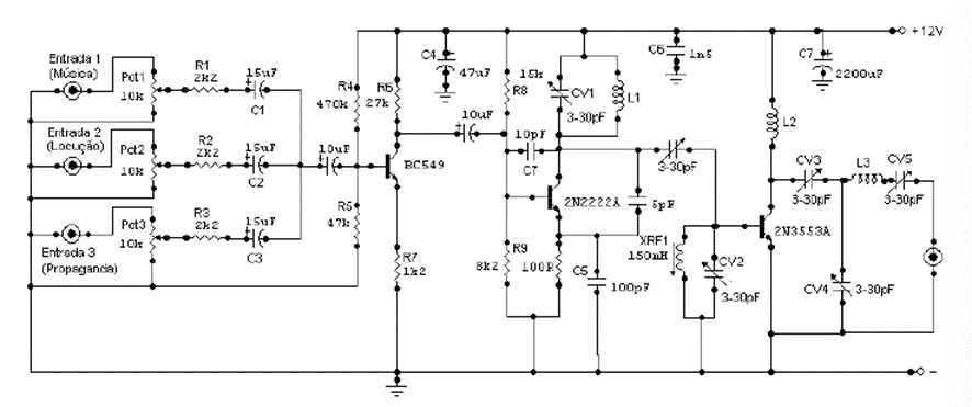
This circuit was sent by our collaborator Adriano Muniz Moura from Pirapora – PG. The transmitter presented above has a power of approximately 1.5Watts that can send its signals tens of kilometers if using a well-sized external antenna. The transistors must have good heat sinks, especially the 2N3553 transistor, which must be adjusted to its maximum power. The power supply must have good filtering and a current of approximately 5A. Potentiometers P1, P2 and P3 are used to adjust the signal level that will be delivered to the 2N2222A oscillator transistor, which can also be replaced by the 2N2218A. The coils are made as follows: L1 is made up of 7 turns of 18-wire with an 8mm diameter without a core.
L2 is formed by 9 turns of wire 18 measuring 1cm in diameter without a core and L3 is formed by 5 turns of wire 18 measuring 1cm also without a core.
The XRF1 RF shock can be replaced by 180mH, 220mH or 250mH and must be of the commercial type, preferably shielded. The 10pF capacitor C7 serves to help the transmitter in its stabilization and can be replaced with an oscillator crystal. To use this type of equipment, current legislation must be observed. The transmitter power must not be changed other than what is stated in the text and diagram. For adjustment use a lamp as a load and use an audio signal during adjustment and use a good frequency meter.