
ART2966S ART155
In a Radio Calling or Pager system, there is a transmitting station that sends coded signals that are only recognized by pre-programmed devices. In older systems, signal recognition triggered a beep that let the subscriber know someone had an important message. In this case, they would find the nearest phone and call the station to receive the message. In modern systems, once the signal is recognized, the receiver digitally records the sent message and displays it on a liquid crystal display screen, as shown in Figure 1.
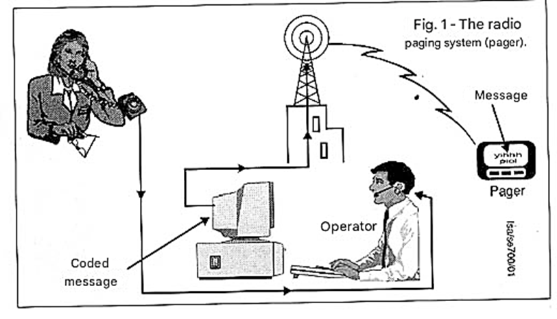
These systems operate in the VHF band and have a good range, only suffering from the same limitations as cell phones in relation to certain areas where there are large obstacles or high levels of interference. For a system that covers a city, we need a very powerful transmitter, several kilowatts, and sensitive receivers.
However, we can have limited-power versions for operation within a domestic or commercial environment. We can even eliminate the need to use a radio transmitter and resort to other means that may even be more efficient depending on local propagation conditions. The idea presented in this article is precisely to use a signal that propagates through the power grid and can thus be captured at any point where there is a power outlet, as shown in Figure 2.
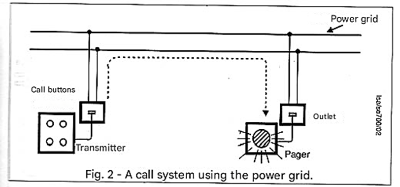
Thus, the user simply needs to connect the receiver to any nearby power outlet and perform the programmed task. When this user needs to be located, a central unit emits a signal that triggers an alarm. When the alarm sounds, the user knows they are being sought by the "central unit," and they simply need to find the nearest phone to find out what the issue is.
A maintenance worker who works in various rooms of a large company, school, hospital, or building can be located at any time by this system. Since the circuit can operate in a fairly wide frequency range, between 40 kHz and 120 kHz, many devices can be used, allowing several employees to have their own "pagers." The circuit's sensitivity is good, and only in special cases where there are separate networks within the same building might range problems occur. For these cases, we provide possible solutions.
CHARACTERISTICS
a) Transmitter
• Power supply: 110/220 VAC
• Operating frequency: 40 to 120 kHz
• Transmitter power: 2 W (typ)
b) Receiver
• Decoder: PLL
• Power supply: 110/220 VAC
HOW IT WORKS
The transmitter uses an oscillator with the well-known 555 integrated circuit to generate a signal at a frequency of 40 to 120 kHz. One of the gates of this integrated circuit is connected as an oscillator where the frequency is basically determined by adjusting a trimpot. In our basic circuit, let's imagine an application with three channels. In this way, there are tree trimpots that must be adjusted independently to very different frequencies when the corresponding call switch is pressed.
The signal from this oscillator is fed to the other three gates of the 4093 integrated circuit, which function as a digital buffer-amplifier. From the output of these three gates, the signal is fed to a power transistor that provides the final signal for application to the power grid. This application is done through a transformer wound on a ferrite core and two polyester capacitors. The power supply consists of a small transformer connected to the power grid, two diodes, and a filter capacitor. No regulation is necessary as the circuit works well with voltages from 6 to 15 Volts. In the receiver, we initially have a transformer with a ferrite core coupled to the power grid by a polyester capacitor. High-frequency signals pass through this transformer and are to be applied to the input of a PLL with the LM/NE567 integrated circuit.
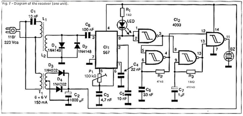
Two diodes in opposition at the input prevent transient or high-voltage surges from the power grid from causing problems to the integrated circuit. The PLL tuning is done using a trimpot that must be adjusted to the corresponding frequency of the transmitter channel. While the PLL integrated circuit does not recognize the transmitter signal, its output remains high, and the indicator LED is off.
Similarly, the IC-2A integrated circuit (one of the gates of the 4093), which is connected as an inverter, has low output. This causes the oscillators mounted around IC-2b and IC-2c to remain disabled. When the PLL circuit recognizes the transmitter station signal (for this it needs at least 50 mV), its output goes low, and the output of the inverter with IC-2b goes high, enabling the oscillator. The result is the production of an intermittent audio tone that is combined at the last gate of IC-2 and fed to a transducer.
The frequency of the beeps is given by C6, while the intermittency is given by C7. The power supply consists of a transformer, two diodes, and a capacitor; no regulation is necessary. However, we note that the maximum supply voltage for the 567 is 10 V. One of the common problems with this system is that high-frequency signals can be blocked or diverted to ground if there is a transformer or other component in their path. This is especially true if the transmitter is connected to one phase and the receiver to another phase of the same installation, as shown in Figure 3.
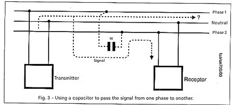
In a case like this, the problem can be solved by connecting a 100 nF x 600 V capacitor between the two phases. The capacitor provides a low-impedance path for the high-frequency signals, which can then pass from one network to another.
ASSEMBLY
Figure 4 shows the complete transmitter circuit.
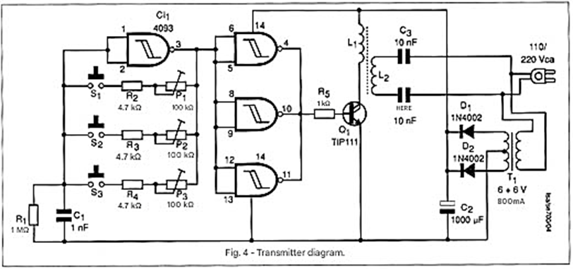
This transmitter can be mounted on a printed circuit board as shown in Figure 5.
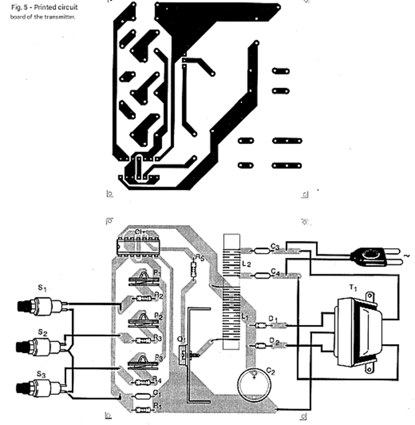
The power transistor can be any NPN Darlington of at least 3 amps and should be mounted on a small heat sink. A power FET can also be used without circuit modifications. The reader should only take care to correctly identify the collector, emitter, and base terminals in the case of the bipolar transistor, and the source, drain, and gate in the case of the FET.
L1 consists of 50 to 100 turns of 26 to 28 AWG wire on a ferrite rod 0.8 to 1 cm in diameter and 10 to 15 cm long. L2 consists of 150 to 200 turns of the same wire wound around L1. Capacitors C3 and C4 must have an insulation voltage of at least 400 V. Electrolytic capacitor C2 must have a working voltage of at least 12 V. For the power supply, the transformer must have a primary winding according to the local power grid and a secondary winding of 6 + 6 V with at least 800 mA. Figure 6 shows how the assembly can be installed in a small box with call buttons to be placed next to an operator or secretary, being activated as needed.
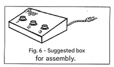
Figure 7 shows the complete diagram of the receiver that uses a PLL.
The assembly of the receiver on a printed circuit board is shown in Figure 8.
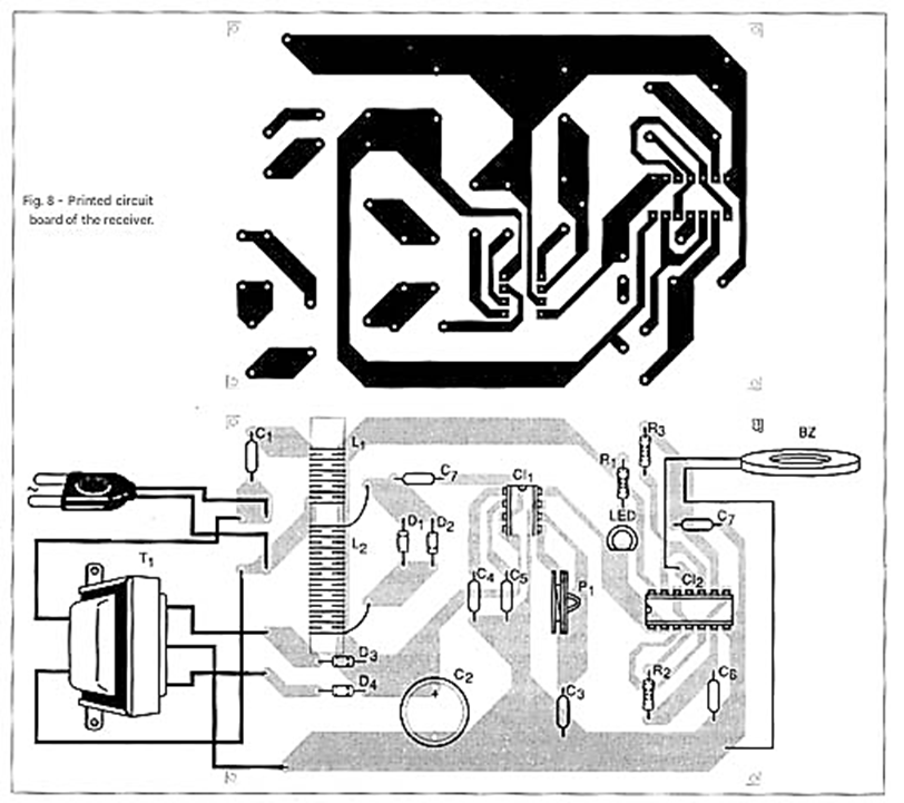
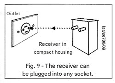
This receiver can be housed in a small plastic box that will be carried by the user and plugged into any power outlet in the work area. Coils L1 and L2 form the high-frequency transformer. L1 consists of 150 turns of 26 to 30 AWG wire on a ferrite rod 0.8 to 1 cm in diameter and 10 to 15 cm long. Coil L2 consists of the same number of turns on L1. Capacitor C1 should be a polyester capacitor with a working voltage of at least 400 V. The transducer consists of a high-impedance piezoelectric ceramic or even a high-impedance microphone capsule. Low-impedance transducers or loudspeakers should not be used for this purpose. The indicator LED can be any color and is optional. The diodes accept equivalents, including those in the power supply.
For the power supply, a small transformer is used with a primary winding according to the mains voltage and a secondary winding of 6 + 6 V with a current starting from 150 mA. If mounted in a sufficiently small box, it can include the plug-in socket as shown in Figure 9, thus making it easier to use.
ADJUSTMENT AND USE
For initial testing, connect the transmitter and receiver to the same power supply. Initially, set transmitter P1 to a position corresponding to 1/3 of its rotation. Then, press S1, which activates the oscillator whose frequency is controlled by P1, and adjust the trimpot on the receiver until you receive the signal. When this occurs, the LED should light up and the oscillator should start.
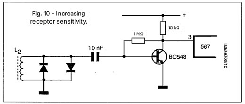
Be careful to tune correctly, as tuning occurs over a wide frequency range when close to the receiver. To fine-tune and avoid a strong signal, keep S1 pressed and move to a more distant room with the receiver, then adjust the trimpot for correct tuning. Figure 10 shows an additional circuit that can be used to increase the receiver's sensitivity if the signal is not received in locations further away from the operating environment.
Once the operation of one receiver is verified, move on to the next unit if your system uses more than one channel. Adjust trimpot P2 to 1/2 of its rotation and then, in the same way, adjust P3 to 2/3. With more than 5 channels, tuning can become difficult because the PLL system can easily trigger when it picks up harmonic frequencies of the fundamental signal emitted. Thus, if one channel is set to 40 kHz and another to 80 kHz, there is a possibility of interference. Ideal frequencies for tuning are 40 kHz, 60 kHz, and 95 kHz.
The values are well separated, and the harmonics are not coincident. If the reader uses a frequency counter for adjustment, it will be easier to achieve, especially if the system uses several channels. If the system does not operate with different phases of the mains, use the capacitor between them. This capacitor can be connected to the power input box itself, as shown in Figure 3 at the beginning of the article.
PARTS LIST
a) Transmitter
Semiconductors:
IC-1 - 4093 - CMOS integrated circuit
Q1 - TIP111 or equivalent - NPN Darlington power transistor
D1, D2 - 1N4002 or equivalent - silicon rectifier diodes
Resistors: (1/8W, 5%)
R1 - 1 M ohms
R2, R3, R4 - 4.7 k ohms
R5 - 1 k ohms
P1, P2, P3 - 100 k ohms - trim pots
Capacitors:
C1 - 1 nF - ceramic or polyester
C2 - 1000 uF/12 V - electrolytic
C3, C4 - 10 nF - polyester 400 V or more
Miscellaneous:
S1, S2, S3 - Normally Open (NO) push-button switches
T1 - Transformer with primary winding according to the... Local network and secondary 6+6 V with 800 mA or more
L1, L2 - Coils - see text
Printed circuit board, mounting box, power cable, wires, etc.
b) Receiver
Semiconductors:
IC-1 - NE567 - PLL integrated circuit
IC-2 - 4093 - CMOS integrated circuit
D1, D2 - 1N4148 or equivalent - general-purpose diodes
D3, D4 - 1N4002 or equivalent - silicon rectifier diodes
LED - Red LED or any common color
Resistors: (1/8W, 5%)
R1 - 1 k ohms
R2 - 47 k ohms
R3 - 1 M ohms or 470 k ohms
P1 - 100 k ohms - trim pot
Capacitors:
C1 - 10 nF - polyester for 400 V or more
C2 - 1000 uF/12 V - electrolytic
C3 - 4.7 nF - ceramic or polyester
C4 - 22 nF - ceramic or polyester
C5 - 10 nF - ceramic or polyester
C6 - 33 nF - ceramic or polyester
C7 - 1 uF - polyester
Miscellaneous:
L1, L2 - coils - see text
T1 - Transformer with primary according to the local network and secondary of 6 + 6 V with 150 mA or more
BZ - Ceramic transducer (see text)
Printed circuit board, mounting box, power cable, wires, solder, etc.


