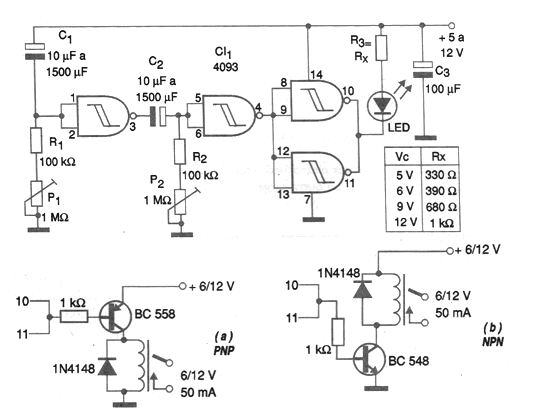
The configuration shown in the figure has been requested a lot by many readers who need a circuit that turns on after a break, and remains that way for a while, then turns off, or still behaves in reverse: turn off after a break, then turn on after another time interval. The two intervals can be adjusted in a range that comes close to 1 hour in potentiometers P1 and P2. The mode of operation of this circuit depends on the type of load driver, which can be done with both NPN and PNP transistors, as shown in the same figure. The time constants of the two drive circuits are given by C1 / R1 and P1 in the first and C2., R2 and P2 in the second. The remaining two ports of the 4093 integrated circuit are used as buffers or digital amplifiers to drive an external load. In the circuit shown in figure 2 we use an LED to indicate the operation, with the values of the resistor in series depending on the supply voltage. The circuit can be supplied with voltages from 5 to 12, depending on the relay used, and the consumption in the condition of not activating the load is very low, of the order of 1 mA or less. The circuit starts its action the moment the power supply is turned on. For successive drives, we recommend connecting in parallel with the switching time capacitors so that the timing starts with these components discharged.