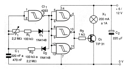
The circuit in the figure causes an incandescent lamp to flash at a speed determined by the setting of P1. The active cycle, or blinking time, is determined by resistor R2. For very short flashes, the resistor can have values between 10 k ohms and 100 k ohms. For longer flashes its value will be between 220 k ohms and 2.2 M ohms. The blinking frequency is set to P1. The power transistor depends on the lamp used. For lamps up to 1 A we recommend using a TIP 31 mounted on a good heat radiator. An interesting application is in automotive signaling systems, where several 200 mA lamps can be connected in parallel.