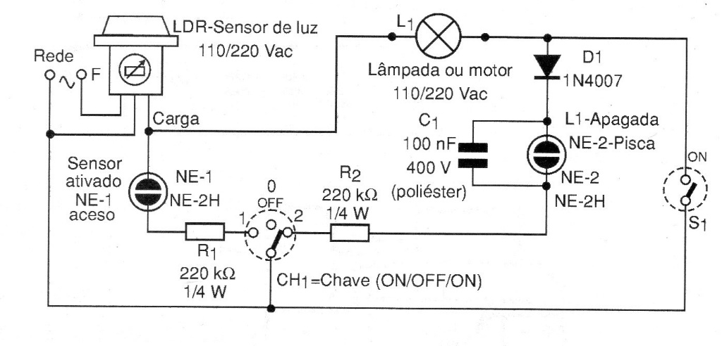
The purpose of this circuit presented in a 2009 documentation is to monitor, by means of neon lamps, indicators of the operation of a load, that is, one or a group of lamps or motor, located at a distance from the point where the command is activated. The power (W) and voltage of the light sensor (LDR) must be observed. This monitoring is operated on the CH-1 switch. As the circuit is designed to work in the absence of light (night), when the sensor trips, an internal relay closes its contact, providing conditions for the circuit to function. Switch S1 must be in the ON position if switch CH-1 is in position 1, with this the neon lamp NE-1 lights up indicating sensor activated and NE-2 remains off. When CH-1 is in position 2, NE-2 lights up, but if S1 is turned off, the L1 lamp goes out or the engine turns off and NE-2 flashes, alerting for the load to be deactivated. For 110 Vac network operation, the R1 / R2 resistors are reduced to 150 k ohms.