
Many designers believe that amplifiers and operational amplifiers are similar and can be used in the same applications without major problems. Even the symbol for these components is the same, but that is precisely where the confusion begins. Operational amplifiers are similar, but only different, using a phrase I often employ in the writing of Saber Eletrônica magazine, to indicate things that look alike, but are actually quite different. See in this article, based on material from TEXAS INSTRUMENTS, why designers should not confuse Operational Amplifiers with Voltage Comparators.
ART140 ART2255S
Operational amplifiers and voltage comparators are used in a wide range of modern circuits, such as in data acquisition and control, interfacing microcontrollers and DSPs. Therefore, the importance of these relatively simple circuits should not be underestimated, and carelessness in choosing the correct configuration or type can compromise important projects in ways that many readers cannot imagine. Operational Amplifiers and Voltage Comparators are represented by the same symbols, as shown in Figure 1, but if we perform an internal analysis of their circuits, we will see that they are quite different, and that is precisely where our analysis begins.
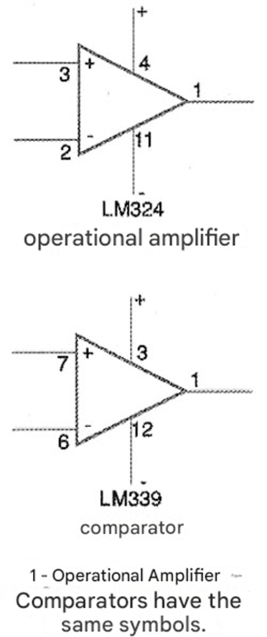
Internal Circuits
Figure 2 shows the internal circuits of a common operational amplifier, such as the LM324.
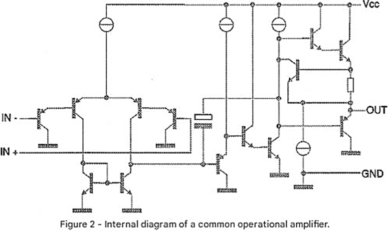
Figure 3, on the other hand, shows the internal circuit equivalent to a voltage comparator, such as the LM339.
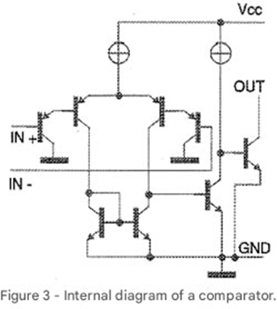
As we can see, the input stages of the two circuits are the same, consisting of differential amplifier stages with inverting and non-inverting inputs. However, it is in the output stage that we find the main differences, which lead to different uses for these circuits and also to their different behavior in many applications. Operational amplifiers are optimized for linear operation, while voltage comparators are optimized for saturated operation.
Thus, if we observe the output stages of these two types of circuits, we will see that while operational amplifiers have outputs with complementary transistors, usually operating in class B, voltage comparators have open-collector outputs. An open-collector output transistor is characterized by having a low collector-emitter voltage (Vce) when switching high current loads. In practice, comparators can have the output of this transistor with only one pin connected to the collector, or we can have circuits where both the collector and emitter pins are accessible, as shown in Figure 4.
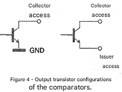
Of course, there are also comparators that, instead of bipolar transistors at the output, use FETs, in which case we will have an open-drain output. Evidently, the component also has its circuit optimized for switching high-power loads and not for linear use.
Comparators
Voltage comparators were created to drive relays. Later, it became clear that the open-drain or open-collector output characteristics of these components made them ideal for implementing power logic functions, such as NAND gates. Figure 5 shows an example of a 4-input NAND gate based on comparators, taking advantage of the open-collector transistors at its outputs.
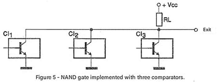
In normal operation, when the output transistors are cut off, their impedance is very high, and when saturated they exhibit a very low impedance. The technique of using open-collector outputs was widely used in digital logic for a long time but has been abandoned by current designers. However, comparators still represent a vestige of this technology that can still be very useful in many projects. What happens is that the "totem pole" outputs used in current logic circuits are much faster but have the disadvantage of not being able to be connected in parallel, which does not occur in the case of comparators. Note: there are comparators that have totem pole outputs and are optimized for both saturated and high-speed operation.
Using the Comparator
Comparators are devices to be used without power supply networks, that is, they are "open loop" type devices. This fact should be very clear when designers are choosing this type of component in a project. Figure 6 shows the basic ways of using voltage comparators.
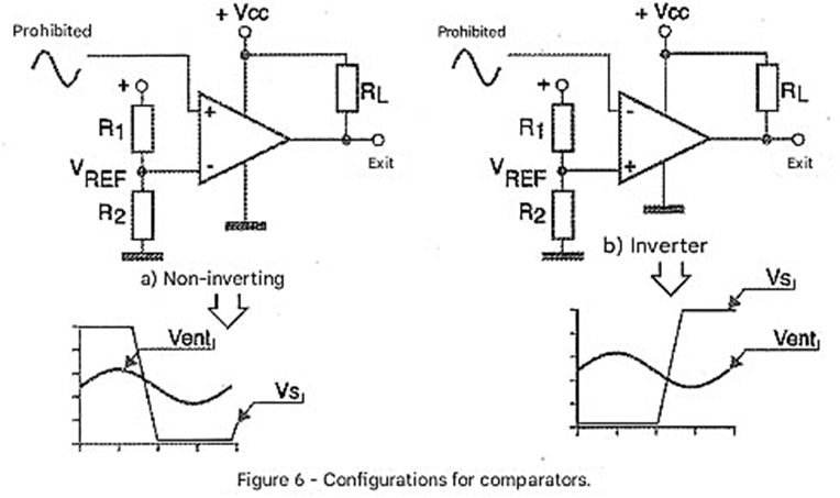
In (a) the reference voltage is applied to the inverting input. When the input voltage, applied to the inverting input, varies between 0 and the reference voltage, the output remains high or the output transistor is cut off (high impedance state). When the voltage exceeds the reference value, the comparator output drops to zero, with the open collector/drain transistor being saturated.
In (b) we have the operation with the reference voltage applied to the non-inverting input. When the input voltage, applied to the inverting input, varies between 0 and the reference value, the output remains low with the open collector/drain transistor being saturated. When the input voltage exceeds the reference value, the circuit switches and the output goes high with the output transistor going cut off.
Note that the high gain of these circuits makes the transition, at the moment the reference voltage is applied to the input, extremely fast. The reference voltage is usually obtained using a resistive divider, but there are other ways to achieve this voltage, which depend on the comparator application.
Window Comparators and Sine Wave to Rectangular Converters
One of the most interesting applications of comparators is obtained by combining them to detect not only the passage of the input voltage through one value but through two, thus delimiting a range or "window" of operation, as shown in Figure 7.
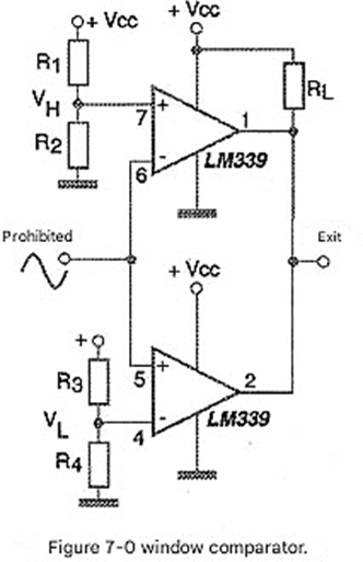
Window comparators use two reference voltages, which can be obtained by resistive dividers in most cases. In the previous edition of Saber Eletrônica magazine, we published an article in which we analyzed the operation of window comparators in more depth. Another important application of comparators is in the conversion of a sinusoidal signal into a rectangular signal compatible with the input of digital logic circuits. How this can be done is shown in Figure 8, noting the need for a symmetrical source.
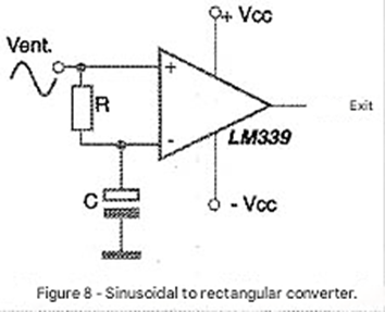
The capacitor charges the average value of the voltage in order to produce the reference and thus ensure that, in input signals with larger amplitudes, we have a duty cycle of the output signal of 50%. Another possible use for comparators is in a feedback loop. We say that the comparator operates in a "closed loop" configuration, as shown in Figure 9.
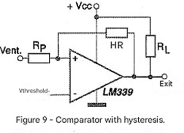
When a comparator operates with a feedback circuit as indicated, it exhibits hysteresis characteristics, as shown in Figure 10.
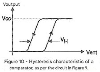
This configuration is particularly interesting when very low frequency signals are used at the input. The hysteresis voltage is typically between 1 and 2% of the supply voltage and can be calculated using the formula:
Vh = [Rp/(Rp+Rh)] x Vcc
Operational Amplifiers
When used without feedback circuits, operational amplifiers behave like voltage comparators. However, operational amplifiers are designed to operate in linear mode. Figure 11 shows the typical Bode curve for an operational amplifier.
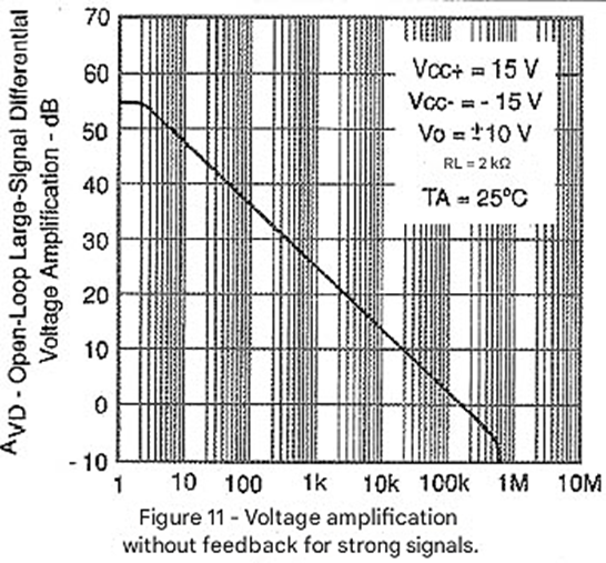
This type of curve is particularly useful for filter design because it provides the response curve of an amplifier as the amplitude of the output signal as a function of the frequency of the signals being processed. Note that, for the amplifier taken as an example, the gain drops by more than 50 dB when we go from continuous signals to signals with a frequency of 1 MHz. Obviously, in any application as an amplifier, it must be remembered that the amplitude of the output signal excursion is limited by the supply voltages.
Since this type of circuit is optimized for a feedback application, the gain must be programmed so that the saturation condition that leads to signal distortion does not occur. When an amplifier is used without feedback, the results obtained can be unpredictable. No manufacturer can guarantee what kind of behavior an operational amplifier will have when used without feedback. Of course, in certain cases, an operational amplifier can be used as a comparator.
A project can be implemented using a specific type of operational amplifier and function perfectly. However, when this operational amplifier is replaced with an equivalent, problems can occur, such as instabilities, increased power consumption, etc. Texas Instruments, in an application note, gives the example of the LM324 operational amplifier, which can be used as a comparator in many cases, but does not switch appropriately in critical applications such as servomechanism control. The problem is exacerbated when the main requirement of the project is a high-speed comparator. The transistors used in the output stages of operational amplifiers are not switching transistors. They are linear devices designed to work with analog signals. In addition to heating up more when driven to saturation, these transistors may not have predictable recovery times, causing circuit instabilities. Even component destruction can occur in a more serious case.
What Not to Do With Operational Amplifiers
The correct use of operational amplifiers involves some simple precautions that can mean the difference between good circuit performance and component burnout. Texas Instruments, in its Application Report SL0A067, lists some of these precautions.
1. Incorrect Connection of Terminals of Unused Stages
Many integrated circuits contain several operational amplifiers that are not always used in their entirety. Figure 12 shows the main errors that occur when unused amplifiers are left in an integrated circuit containing several of them.
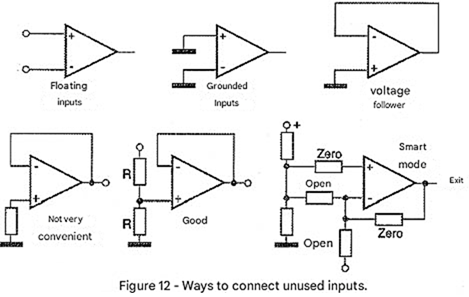
Note that the correct methods involve polarizing the inputs with specific voltage levels.
• Floating inputs - leaving the inputs free, with the high gain it possesses, noise can cause the circuit to oscillate between supply voltages, easily saturating. In this process, the oscillation can be responsible for the production of high-frequency noise.
• Grounding the inputs simultaneously - it cannot be guaranteed that there is no common-mode voltage in this configuration, as small differences in track lengths can be responsible for this. This small voltage can be responsible for saturating the operational amplifier, with unpredictable effects.
• Connecting as a voltage follower - this is not an appropriate solution, as the designer must ensure that the amplifier stabilizes in an operating condition and remains there. However, this connection can cause component heating and increase power consumption.
• Not very convenient - this approach can lead the amplifier to output at one of the supply voltages.
• Good - In this system, the inverting and non-inverting inputs are maintained at half the potential between the positive and negative lines, that is, at ground when using a symmetrical source. If a virtual ground exists in the system, it can be used in this connection.
• Smart mode - the smart designer, according to Texas Instruments, anticipates the possibility of the system changing in the future. Thus, by removing the resistors and using jumpers, unused operational amplifiers can be utilized.
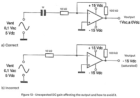
2. DC Gain
Another cause of problems in circuits using operational amplifiers is that designers forget about the effects of DC components that may be present in the signals. The presence of a DC component can change the level of the output signal in the quiescent condition, as illustrated in Figure 13.
3. Constant Current Source
One fact noted by Texas Instruments when verifying the applications of its components is the misuse of the current sources in operational amplifiers. In certain applications, the load is connected to the end of a cable, which is connected to the circuit, as shown in Figure 14.
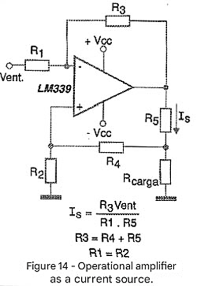
When the cable is disconnected, the amplifier experiences strong positive feedback, bringing its output to the potential of the negative power supply line.
Texas Instruments Products
Texas Instruments recommends against using non-feedback operational amplifiers as voltage comparators. Problems already analyzed can occur. However, many designers are tempted to use integrated circuit-free operational amplifiers containing two or four units as comparators, and this can lead to problems. Considering this possibility, Texas Instruments offers some products that can be very interesting for those who need operational amplifiers and comparators in the same application.
These are combined integrated circuits (combo) that contain operational amplifiers and comparators in the same package. With these ICs, the designer can save time, space on the printed circuit board, and more than that: save on the final cost of the product being developed.
TLV2302/TLV2304
These components combine in a single package 1 operational amplifier and 1 open-collector comparator (TLV2302) or 2 operational amplifiers and 2 open-collector comparators (TLV2304) in a single package. Among the characteristics to be highlighted for this component is its low operating voltage of 2.5 V, which makes it compatible with the operation of low-power microcontrollers such as the MPS430.
TLV2702/TLV2704
These components combine in a single package an operational amplifier and a comparator with push-pull output (TLV2702) or two operational amplifiers and two comparators with push-pull output (TLV2704). The minimum operating voltage of 2.5 V makes it compatible for use with ultra-low power microprocessors such as the MSP430.
Conclusion
Operational amplifiers may seem the same as comparators, but in reality, they are different. Do not be tempted to use cheap or off-the-shelf operational amplifiers in an IC that has been used for another purpose to implement comparators. The results can be catastrophic in a project.
Use appropriate components or take advantage of the combined solutions that Texas Instruments offers, with components that combine both functions in the same package. More information about the components mentioned in this article, including complete datasheets in PDF format, can be downloaded from the Texas Instruments website at: http://www.ti.com


