
The photometer displayed can be used in the science lab, in physics experiments or in color comparisons.
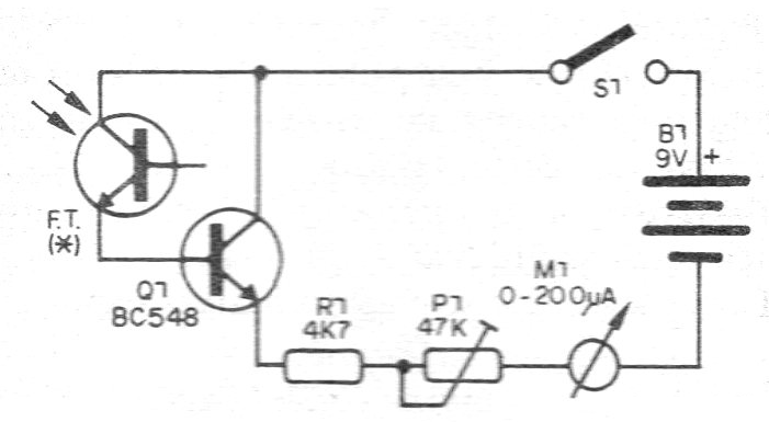
The circuit uses a photo-transistor as sensor and has a transistor amplifier for greater sensitivity.
The indicating instrument may be a microammeter from 200 uA to 1 milliammeter of 1 mA.
In figure 1 we have the complete diagram of this photometer.
The assembly can be made from a small terminal strip as shown in figure 2.
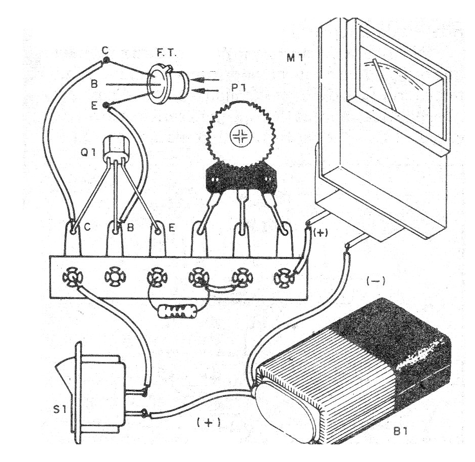
Any common photo-transistor can be used in this mount and even a photo-diode.
The resistor is 1/8 W with any tolerance and equivalent transistors can be used.
When mounting, simply observe the positions of the components, especially in the case of photodiodes that must be reverse polarized.
Material list
Q1 - Any photo-transistor
Q1 - BC548 - NPN general purpose transistor
P1 - 47 k ohms - trimpot
R1 - 4k7 ohms - resistor - yellow, violet, red
B1 - 9 V - battery
S1 – On-Off switch
Several:
Terminal bridge, battery connector, mounting box, wires, solder, etc.


