
ART4005S ART5443
This project is interesting not only for readers who still have an old computer, but for everyone, as it can be controlled by a microcontroller or other means. Simply make the connections and write the program in the appropriate language.
If you want to achieve different sounds, one or more astable oscillators can be replaced with double-T oscillators.
Perfect for those who enjoy making modifications. (Figure 1)
How it works:
Bits D0, D1, and D2 of the computer's parallel output (LPT1) were used to address a CMOS CD 4051 demultiplexer circuit, containing one input and eight outputs.
The input is connected to VCC. Thus, at each address accessed, a logic-high level will be generated at the output, saturating the NPN transistor BC 548, powering one of the seven oscillator circuits built with the NE 555 ICs in an astable audio frequency configuration.
The first output of the demultiplexer will not be used, as it will remain at a logic-high level whenever address 000 is accessed, thus becoming the circuit's standby state.
Bit A3 of LPT1 was used to turn an eighth oscillator on and off with the NE 555 integrated circuit; this bit is connected directly to the reset pin (pin 4).
The ninth circuit with the 555 IC has its output signal (pin 3) connected to the positive terminal of a capacitive load (two 470 uF capacitors connected in series), which are charged through the internal resistance of the fifth oscillator, where the negative terminal of the capacitor combination is connected.
When the power to this fifth oscillator is shortly turned on and then cut off (as we will see later in the program explanation), these capacitors discharge instantly, creating a kick drum sound. This effect turns on and off each time the two-output sequential counter receives a clock pulse on pin 14 from bit D7 of LPT1.
The eighth and ninth oscillators require a power supply voltage between 6 and 9 volts for proper operation, as they are directly controlled by the parallel port output bit, where the high logic level is 5 volts. Furthermore, the system that produces the kick drum effect also depends on this factor.
According to tests performed with the prototype on the bench, if the voltage is below 6 volts, the kick drum effect does not work, and above 9 volts, the eighth oscillator triggers, emitting a continuous tone.
Assembly:
Figure 2 shows the device diagram.
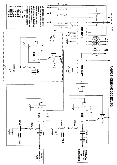
The inputs identified in the schematic diagram as A, B, C, D, and H, which control the circuit's operation, must be connected to pins 2, 3, 4, 5, and 9, respectively, corresponding to bits D0, D1, D2, D3, and D7, on the computer's LPT1 parallel output using a cable with a DB25 connector.
The input identified as +VCC 6V to 9V must be connected to the positive terminal of a power supply between 6 and 9 volts × 250 mA. (The prototype used a 7.5 volt × 300 mA telephone power supply.) The negative terminal of the circuit's power supply must also be connected to one of the pins 18 and 25 of the DB25 connector (GND).
The outputs labeled 1, 2, 3, 4, 5, 6, and 7 are connected to seven oscillators, identical to the one within the dotted field highlighted in the circuit and already connected to pin 2 of the CD 4051 IC. The resistor and capacitor values for each oscillator are specified in the table in the schematic diagram.
The audio output can be connected directly to the auxiliary input of an amplifier. All resistors are rated for 1/8 W. All capacitors are rated for 16 volts or higher.
The two 470 uF × 16 volt capacitors used at the output of the ninth oscillator for the kick drum effect should preferably be bipolar.
The transistors are all general-purpose NPN BC 548.
List of materials
01 CD 4051 integrated circuit
01 CD 4017 integrated circuit
09 NE 555 integrated circuit
08 BC 548 transistor (NPN general purpose)
04 120 ohm × 1/8 W resistor
03 1 k ohm × 1/8 W resistor
02 470 k ohm × 1/8 W resistor
02 10 k ohm × 1/8 W resistor
01 2.2 k ohm × 1/8 W resistor
01 4.7 k ohm × 1/8 W resistor
01 15 k ohm × 1/8 W resistor
01 22 k ohm × 1/8 W resistor
01 Resistor 27 k ohms × 1/8 W
01 Resistor 33 k ohms × 1/8 W
03 Polyester capacitor 220 nF × 100 Volts
07 Polyester capacitor 1 nF × 100 Volts
02 Electrolytic capacitor 470 uF × 16 Volts (preferably bipolar type)
08 Electrolytic capacitor 3.3 uF × 16 Volts.
Miscellaneous:
01 Cable with male DB 25 connector.
01 Power supply 7.5 Volts × 300 mA (see text)
01 Female connector for audio output (according to the input connector of the amplifier to be used)
01 Cable to connect to the amplifier
Printed circuit board for assembly.
Wires
Soldering
Box to house the assembly.
Old computer with access to the MS DOS prompt.
Assembler Program:
0100: MOV DX, 0378
0103: MOV AX, 0800
0106: INT 21
0108: CMP AL, 1B
010A: JE 011B
010C: OUT DX. AL
010D: CALL 011D
0110: MOV AX, 0000
0113: OUT DX, AX
0114: CALL 011D
0117: LOOP 0100
0119: LOOP 0100
011B : INT 20
011D: PUSH CX
011E: PUSH DX
011F: MOV CX, 0AAA
0122: MOV DX, 0AAA
0125: DEC DX
0126: JNZ 0125
0128: DEC CX
0129: JNZ 0122
012B : POP DX
012C: POP CX
012D: RET
In figure 4 images of the program.
Test and use
Recalling the DEBUG commands to type the program and run it from the MS DOS prompt on the old computer.
Access the MS DOS prompt and type the following commands:
DEBUG (and the Enter key to enter Assembler programming mode)
A (and the Enter key to write the program)
(Type the program)
After typing the last command, press the Enter key twice.
G (and the Enter key to run the program)
(From now on, the program will wait for any key press to send the corresponding byte to the computer's parallel output and control our circuit)
ESC (and the Enter key to end the program)
Q (and the Enter key to exit DEBUG and return to the MS DOS prompt)
Now that the program is typed and running, connect the device to the computer and amplifier, and turn on the power supply.
For each key press, a different sound will be generated. The F11 key turns the bass drum sound effect on and off.
Step-by-step explanation of the program:
MOV DX, 0378 (Command that transfers the address of the LPT1 parallel output to the DX register) Note: Check in your computer setup whether the address of your parallel output is 0378, 03BC, or another.
MOV AX, 0800 (Command that transfers data 0800h to the AX register to use function number 08 of the INT 21 instruction)
INT 21 (This is a DOS interrupt instruction that allows the reading of any available key on the keyboard)
CMP AL, 1B (Command that compares data 1Bh, which corresponds to the ESC character on the keyboard, with the contents of the lower part of the AX register)
JE 011B (If the key typed is the ESC key, this command immediately jumps the program to the INT 20 instruction, whose address is 011B, thus ending the program)
OUT DX, AL (Output command that sends the contents of the lower part of the AX register, corresponding to the hexadecimal code of the key typed, to the DX register, whose address is the computer's parallel output LPT1, as specified at the beginning of this program)
CALL 011D (command that tells the program to execute the subroutine at address 011D, since it loads 011D into the IP register)
MOV AX, 0000 (Command that transfers the data 0000 to the AX register)
OUT DX, AX (Output command that transfers the data 0000 to the DX register, whose address is the computer's LPT1 parallel output)
CALL 011D (Command that tells the program to execute the subroutine at address 011D, since it loads 011D into the IP register)
LOOP 0100 (Command that returns the program to the beginning, repeating all previous instructions)
LOOP 0100 (This repeated command ensures that if a failure occurs due to high program turnover, it will fall back to the same instruction, thus preventing the program from being unintentionally terminated, as the next INT 20 instruction would terminate the program. (Note: This problem occurred during prototype testing while only one LOOP instruction was still in use.)
INT 20 (Command that terminates the program)
PUSH CX (Command that places data from the CX register on the stack)
PUSH DX (Command that places data from the DX register on the stack)
MOV CX, 0AAA (Command that transfers data 0AAA to the CX register)
MOV DX, 0AAA (Command that transfers data 0AAA to the DX register)
DEC DX (Command to decrement data contained in the DX register)
JNZ 0125 (Jump instruction to jump to the address 0125 while the contents of DX are not equal to zero)
DEC CX (Command to decrement the data contained in the CX register)
JNZ 0122 (Instruction for the program to jump to address 0122 while the contents of the CX register are not equal to zero)
POP DX (Instruction that allows you to pop the data contained in the DX register from the stack)
POP CX (Instruction that allows you to pop the data contained in the CX register from the stack)
RET (Instruction that returns the program to the first instruction after the CALL)
As you can see, this control program is always waiting for a keystroke. When this occurs, it transfers the corresponding byte to the computer's LPT1 parallel output for a moment and then returns to a fully low logic level, waiting for another key to be pressed, except for the ESC key, which was configured to end.
With the binary data available on the computer's parallel output, we control the electronic circuit through bits D0, D1, D2, D3, and bit D7, which is responsible for controlling the bass drum on and off via the F11 key.
The MS DOS operating system prompt is not available on current computers, nor is the LPT1 parallel output port. Now that we have enjoyed this incredible trip down memory lane, we are back with our circuit, which can be perfectly controlled through inputs A, B, C, D, and H connected to modern equipment programmed in another language.
I hope you enjoyed the article.
See you next time!
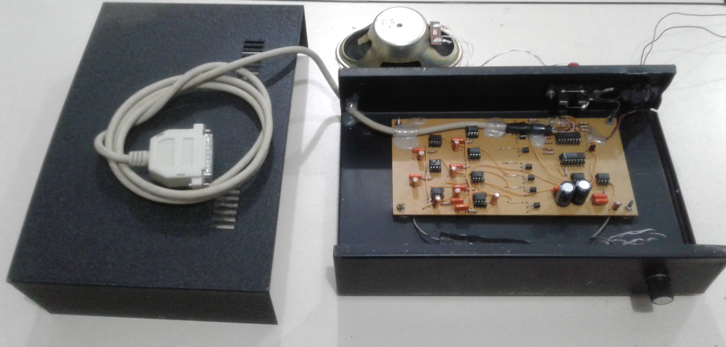
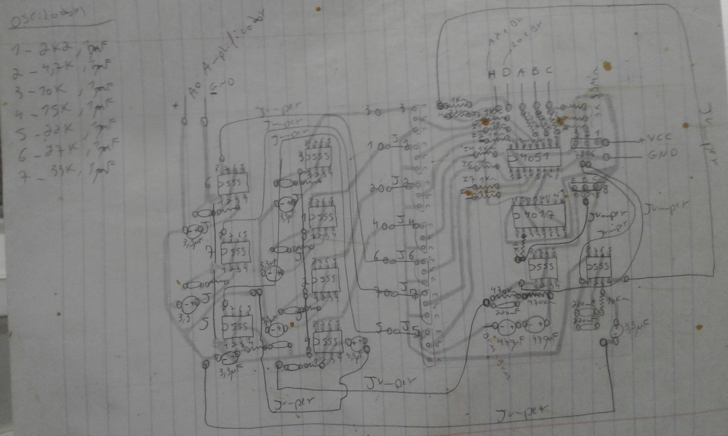
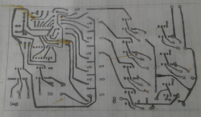
Below is the circuit, photos of the prototype, the typed program, the printed circuit board that served as the chassis for the assembly, and also an mp4 audio that I recorded to demonstrate some sounds that the device produces when pressing each key and an example of a sound beat that we can make.


