
With this unit it is possible to check the state of high voltage capacitors such as polyester and ceramic, and others with a working voltage of at least 200 V if the network is 110 V, and 400 V if the network is 220 V. The test also allows to detect insulation faults in cables, connectors, etc. when a neon light comes on. Even a resistance of tens of megohms is sufficient to cause the lamp to light, indicating the abnormality of the component.
The circuit operates with an extremely low current, and as it is connected directly to the power grid, it must be considered by the assembler in order to isolate all its parts well.
Mounting in a closed box is recommended and should always be connected to the component under test with the plug out of the outlet.
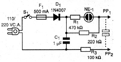
In figure 1 we have the complete diagram of this insulation tester.
In figure 2 we have the arrangement of the components in a terminal strip that serves as a chassis.
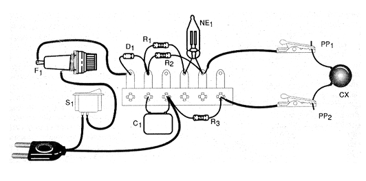
The neon lamp can be of any type and the resistors are 1/8 W or larger.
The diode used is the 1N4007 for the two power grids (110 V or 220 V).
For the 110 V network the 1N4004 can also be used.
The capacitor C1 is metallized polyester having a working voltage of at least 200 V if the network is 110 V and at least 400 V if the network is 220 V.
To use the unit, simply push the probes to the terminals of the capacitor or component under test.
Only components with a voltage of at least 200 V can be tested if the network is 110 V and double if the network is 220 V.
If the lamp lights up in the test and remains so, it is a sign that there is a leak in the capacitor under test or insulation problems if the tested component is a cable or connector.
Momentary firing (when the appliance is switched on) is normal when capacitors over 10 nF are tested.
It will be interesting to have some common capacitors for the demonstration.
These capacitors can be easily achieved in out-of-use electronic equipment.
The interesting thing is that the device itself will serve to indicate whether or not they are in good condition.
WHAT TO EXPLAIN
Capacitors are studied in the medium course in physics.
A practical demonstration of its operation is very interesting and this can be done with the test that we describe.
An interesting possibility for teachers is to mount a capacitor using aluminum foil or even a Leyden bottle.
In the explanations it must be taken into account that:
* The capacitors should isolate the current and therefore should not turn on the neon lamp. Explain how capacitors work and how wire insulation works.
Explain how the neon lamp works. This topic is interesting if associated with ionization, subject studied in chemistry and physics in high school.
* Place the test leads in contact with the water in a glass. The lamp should light up indicating that it is electrically conductive. Experiment with various materials to detect good drivers, poor drivers and good insulation.
Note: common water is conductive due to the presence of mineral salts and impurities. Pure water is a good insulator.
MATERIAL LIST
D1 - 1N4007 - silicon diode
F1 - 500 mA Fuse
S1 - Single switch
C1 - 1 uF / 200 V - polyester capacitor - see text
R1 - 470 k ohms - resistor - yellow, violet, yellow
R2 - 220 k ohms - resistor - red, red, yellow
R3 - 100 k ohms - resistor - brown, black, yellow
NE-1 - common neon lamp
PP1, PP2 - Probes
Cx - capacitor or component under test
Several:
Terminal block, fuse holder, power cable, mounting box, alligator clips or probes, wires, solder, etc.


