
With this circuit it is possible to transform your amplifier into an ordinary AM receiver with excellent sound quality. The fidelity will of course depend on the characteristics of the amplifier used.
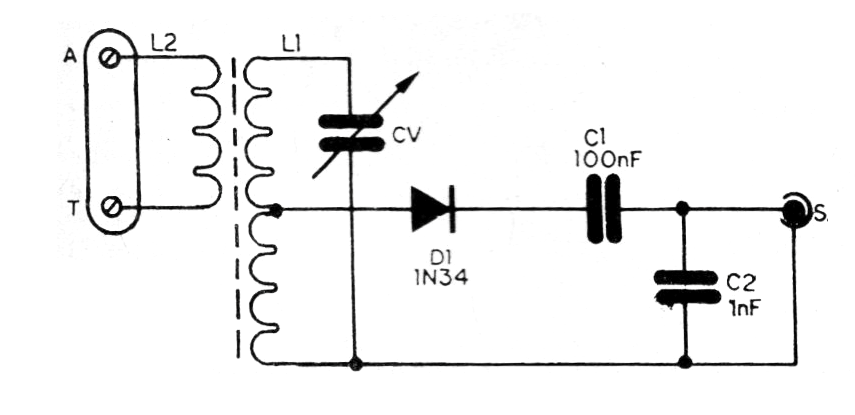
The circuit consists of a step of tuning and detecting good sensitivity signals, without the need for active circuits, since the volume will be controlled in the amplifier itself. The complete tuner circuit is shown in figure 1.
In figure 2 we have the tuner assembly on a small terminal strip. The assembly can be installed in a small plastic box. The output can be a plug according to the input of the amplifier.
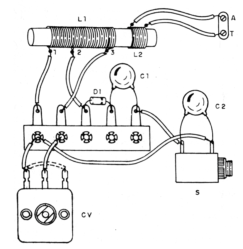
For strong stations the antenna is a piece of wire from 1 to 3 meters long.
The coil L1 is formed by 40 + 40 turns of wire 28 in a ferrite rod 15 to 30 cm long and approximately 1 cm in diameter. L2 consists of 10 to 20 turns of the same wire next to L1. The variable capacitor can be obtained from any old AM radio.
Material list
D1- 1N34 or equivalent - germanium diode
L1, L2- Coils- see text
CV – Variable capacitor - see text
C1- 100 nF- ceramic capacitor
C2- 1 nF- ceramic capacitor
Miscellaneous: terminal strip, ferrite wand, enameled wires, wires, solder, mounting box, etc.


