
Here is a simple circuit, made from scrap material, ideal for those who like to make different experiments. This is an oscillator which has a frequency that depends on light focusing on a sensitive element.
The sensitive element may be an LDR or even a common phototransistor, with less sensitivity. The circuit can be powered with 2 or 4 batteries.
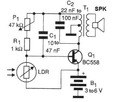
What we describe is a Hartley type oscillator whose frequency is influenced by the feedback circuit, where we put a sensor. This sensor consists of a common photoresistor, a component whose resistance depends on the intensity of the light incident on its sensitive surface.
We can use this circuit to make demonstrations about the principle of photos alarms and photosensors operations. In Figure 1 we have the complete diagram of the solar oscillator.
The assembly of the components is based on a terminal bridge as shown in Figure 2.
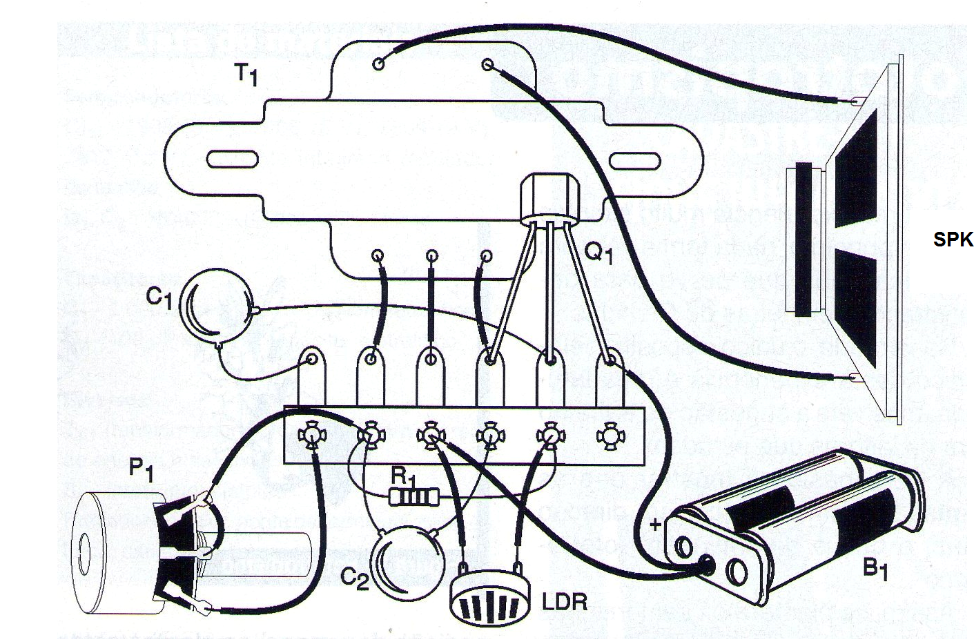
The T1 transformer is the only critical component of the assembly. We use an output transformer taken from an out of use transistor radio. This component is easily identified by being connected to the loudspeaker. There is usually another transformer in the circuit that is not connected to the speaker.
This transformer, the driver, is not suitable for this project.
The capacitor C1 may have values between 10 nF and 100 nF and is of any type. The same is true for C2 which may have values between 22 nF and 100 nF. The 1/8 W resistor and its values can be between 47k ohms and 470k ohms.
The loudspeaker can also be of any type with 8 ohms of impedance.
Two or four small batteries may be used in the power supply. The transistor admits any equivalent: PNP transistors of general purpose silicon can be used harnessed even from the own radio where the transformer has been withdrawn.
Even old germanium transistors can be tried. The only important point in connecting the transistor is that we need to know the arrangement of its terminals in order to identify the collector, emitter and base.
For the sensor it may use any common LDR or a power transistor, such as 2N3055, from which the top of the housing has been withdrawn in order to expose the semiconductor chip to light.
To test the unit, simply insert the batteries and adjust P1 for sound.
After the oscillator is set to "beep", shade the sensor and see how it influences the tone of the sound produced.
To have a directional action of the sensor, install it in a cardboard tube. The best operating point occurs at the extremes of the oscillation range.
MATERIAL LIST
Semiconductors:
Q1 - BC558 or any general purpose PNP transistors
Resistors:
LDR - common photo resistor
R1 - 1k ohms - brown, black, red
P1 - 47 k ohms - potentiometer
Capacitors:
C1 - 10 to 47 nF - polyester or ceramic
C2-22 nF to 100 nF - polyester or ceramic
Miscellaneous:
SPK - 8 ohms x 10 cm - common speaker
T1 - Transistor output transformer - see text
B1 - 3 or 6 V - 2 or 4 small batteries
Terminal bridge, battery holder, assembly box, wires, welder, etc.


