
This circuit can be used in decoration, to give special effects on toys and even key chains or on the dashboard of a car to simulate an alarm.
The basis of the design is a TLC7555 CMOS integrated circuit, which is the equivalent of the conventional 555 in a low power consumption technology with high input impedance.
With this circuit we can make an LED pulse at regular intervals with an extremely low consumption, which means that the batteries will have great durability.
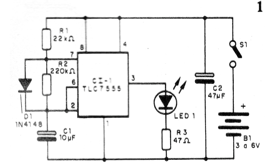
In our circuit, the interval between the blinks is determined by R2 and the duration by R1. The frequency is is controlled by C1 which can be changed in the range of 1 to 100 uF, depending on the application.
In figure 1 we have the complete diagram of this blinker.
In figure 2 we have the arrangement of the components on a printed circuit board.
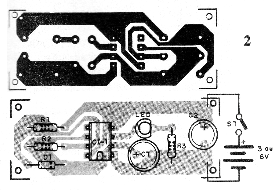
The LED can be any color, but if the power is 3 V, red is more advisable. The diode supports equivalent and the integrated circuit can be installed in socket.
A conventional 555 can also be used for 5 V or more power supplyss, but consumption will be higher.
To test the device simply turn on the power. It is convenient to keep the ratio of values of the resistors greater than 10 to 1 in order to obtain the minimum consumption.
Material list:
CI-1 - TLC555 - integrated circuit
D1- 1N4148 or equivalent - diode
LED - LED common
R1- 22k ohm x 1/8 W - resistor - red, red, orange
R2 - 220 k ohm x 1/8 W- resistor - red, red, yellow
R3 - 47 ohm x 1/8 W - resistor - yellow, violet, black
C1 - 10 uF - electrolytic
C2 - 47 uF - electrolytic
B1- 3 to 6 V - 2 to 4 batteries
S1 - On/off switch
Miscellaneous:
Printed circuit board, battery holder, mounting box, wires, solder, etc.


