
This siren can equip your bike, rock carts and other toys with a sound similar to those of police vehicles and firemen. Another utility for this circuit would be as part of warning or alarm.
The circuit works in its basic version with 4 common batteries, and by switching Q2 to a higher power transistor such as TIP32, we can power it with 12 V, obtaining greater sound intensity.
In the 12 V version, transistor Q2 must be provided with a small heat radiator.
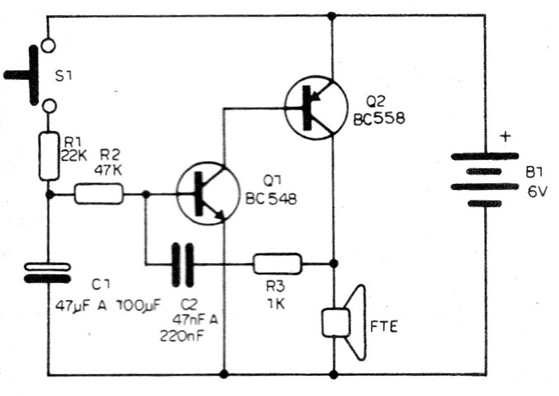
When we press S1, the capacitor C1 charges slowly through the resistor R1 obtaining increasing tone of sound (becoming more and more acute).
When we release S1, the capacitor C1 discharges through the circuit, making the sound decrease until it stops.
By pressing and releasing the switch, we can manually simulate the effect of a siren.
It is not necessary to use general switch, because when completely discharged, C1 causes no sound and current consumption practically reduces to zero.
All components are common, including there are some that can be availed from junk.
ASSEMBLY
In figure 1 we have the complete diagram of this apparatus.
The assembly on a terminal strip is shown in figure 2.
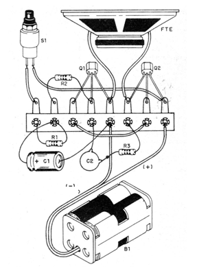
C1 can be electrolytic, from 47 to 100 uF, with working voltage between 6 and 50 V. C2 can be polyester, styroflex or ceramic, with values between 47 and 220 nF.
Experiment with the two capacitors until you get the best effect.
The resistors are 1/8 or 1/4 W with any tolerance and, for greater sound yield, we suggest the use of a speaker of at least 10 cm diameter mounted in a plastic housing.
For the batteries, support must be used and S1 consists of a common push-button.
TEST AND USE
When the unit is assembled and the assembly is checked, place the batteries in the holder.
Press S1; the unit should immediately emit sound.
Releasing S1, it will still do it for a few seconds with the tonality decreasing.
The emission time can be changed with the change of C1.
The hue is determined by C2.
Experiment by changing these two components.
MATERIAL LIST
Q1 - BC548 or equivalent - general purpose NPN transistor
O2 - BC558 or equivalent - general purpose PNP transistors
FTE - 8 ohm speaker x 1ocm
S1 – push-button
B1 6 V - 4 small or medium size batteries
R1 22k - resistor (red, red, orange)
R2 47k - resistor (yellow, violet, orange)
R3 1k - resistor (brown, black, red)
C1 47 to 100 uF - electrolytic capacitor
C2 - 47 to 220 nF - capacitor - see text
Several:
Terminal strip, mounting box, battery holder, wires, clamp for fixing, screws etc.


