
The circuit shown in figure 1 activates a small indicator lamp that will blink when ambient light is reduced. The trigger point of the circuit is determined by P1 and the flashing frequency is set to P2.
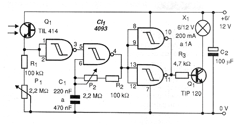
The sensor is a common photo-transistor that, for greater efficiency, must be mounted on a tube and pointed to the place where the light is to be monitored. This sensor can not receive the light from the lamp itself that is fed so that no feedback occurs, capable of destabilizing the circuit.
For lamps up to 50 mA a BC548 can be used and for lamps of 200 mA to 1 A, a power Darlington, such as TIP120, mounted on a heat radiator must be used.
Consumption at rest is very low. Consumption, when activated, depends only on the lamp used. Thus, for supplying larger bulbs, source or battery must be used.
In figure 2 we have a suggested circuit board for mounting the night switch. In the design of the board we envisage the use of the TIP120. Equivalent transistors may have different terminals requiring board changes.
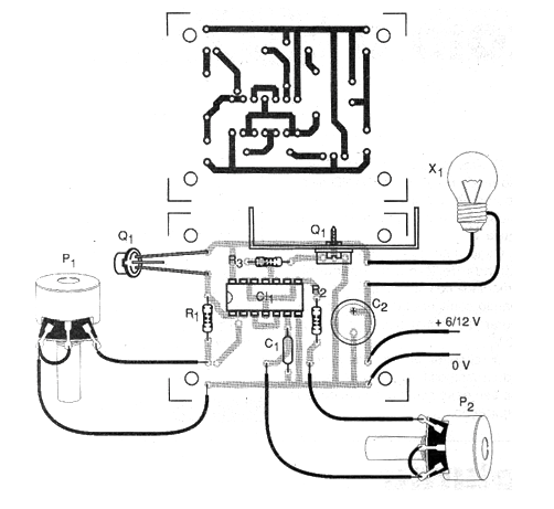
The supply voltage must be according to the used lamp and can be between 6 and 12 V for common applications.
To adjust the device, simply cover the sensor and operate on P1 to determine the trip of the circuit. Then, P2 is set to the flashing frequency.
Material list
Semiconductors:
CI-1 - 4093 - integrated circuit
Q1 - TIL414 or any ordinary photo-transistor
Q2 - TIP120 - NPN power Darlington transistor - see text
Resistors: (1/8 W, 5%)
R1, R2 - 100 k ohms - brown, black, yellow
R3 - 4.7 k ohms - yellow, violet, red
P1, P2 - 2.2 M ohms - trimpots
Capacitors:
C1 - 220 nF to 470 nF - ceramic or polyester capacitor
C2 - 100 uF x 12 V - electrolytic capacitor
Several:
Printed circuit board, mounting box, power supply (batteries, source or battery), wires, solder, etc..


