
Sequential signals in patterns determined by the diode arrangement of the circuit of Figure 1 can be used to control machines in a few scheduled operations.
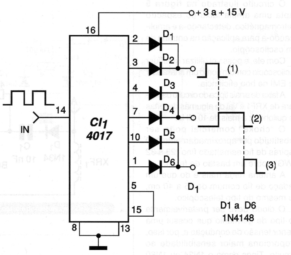
We then have the possibility of developing a micro-CLP for control of devices that can be activated from relays connected to the output of the diodes. In this example we have the drive using 6 outputs with 3 final drives given by the diodes.
This means drive cycles for each output equivalent to 1/5 of the external clock cycle. However, based on the 10 outputs and different combinations of diodes we can get more or less cycles and with different durations, according to the desired control.
There is also the possibility of cascading two or more 4017, thus obtaining 18 or 27 control outputs, since in the cascade only 9 outputs can be used. The outputs of the 4017 provide 0.88 mA currents with 10 V power, which value must be taken into account when external control devices are triggered.
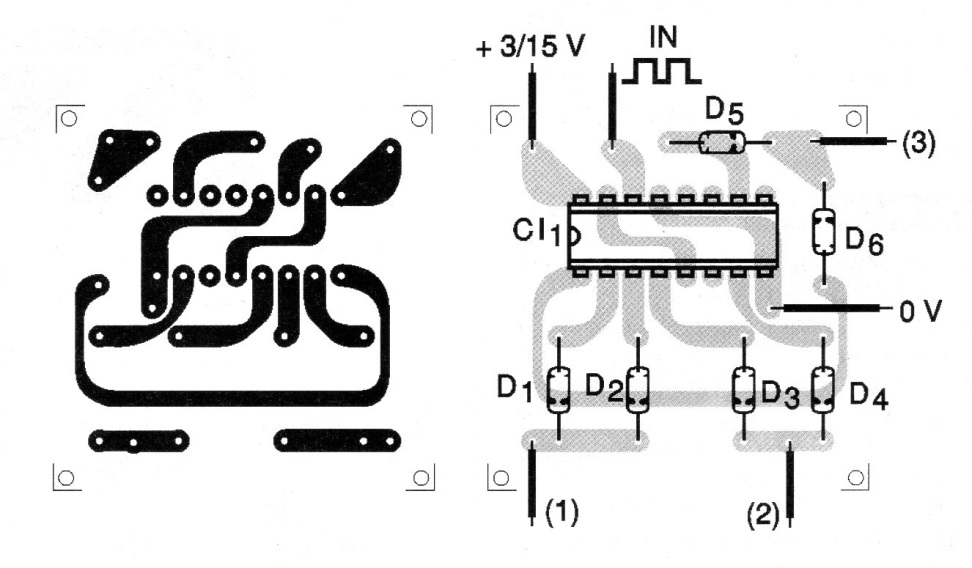
In figure 2 we have a suggested circuit board for the specific case of the given circuit as an example.
Remember that the maximum input frequency is around 7 MHz for a power supply with 10 V. There is no limit to the minimum frequency and a splitter with the 4020 can be used to obtain extremely long periods of operation for the controlled circuits.
MATERIAL LIST
CI- 4017 - CMOS integrated circuit
D1 to D6 - diodes 1N4148 or equivalent
Several:
Printed circuit board, solder, etc.


