
This design is very useful for the home or workshop because it allows controlling the brightness of incandescent lamps (not suitable for other types of lamps), the temperature of heaters or the speed of motors. The TRIAC supports 4 amp currents, which means maximum power of up to 440 W in the 110 V and 880 W power grid in the 220 V power grid. For this assembly you will need the following material:
MATERIAL LIST
Q1 - 2N2646 - unijunction transistor
TRIAC - TIC206B (110 V) or TIC206D (220 V)
D1 to D4-1N4004 - silicon diode (110 V) or
1N4007 (220V)
T1 - TP 1: 1 Pulse Transformer
R1 - 470 ohm - resistor (yellow, violet, brown)
R2 - 10 k ohm x 2 W (110 V) or 22 k ohm x 5 W (220 V) - wire resistor
R3 - 10 k ohm - resistor (brown, black, orange)
R4 - 47 k ohm - resistor (yellow, violet, orange)
C1 - 100 nF - polyester capacitor
Miscellaneous: printed circuit board, power outlet, power cable, mounting box, heat radiator for TRIAC, etc.
ASSEMBLY
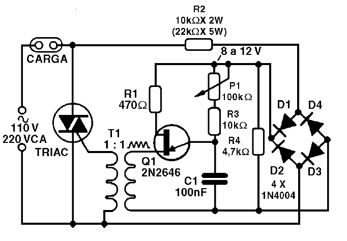
In figure 1 we have to the complete diagram of the control.
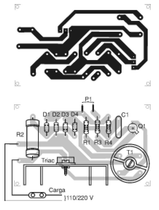
In figure 2 we have the printed circuit board for the assembly.
The pulse transformer can be home-made if the original is not found. In a ferrite rod approximately 1 cm in diameter and 5 cm in length, wind 100 turns of enamelled wire 28 to the primary wire, and then wind up another 100 turns from the same wire to the secondary wire.
To use the appliance is simple: connect a light bulb to the output and turn the potentiometer checking that the power control is from zero to the maximum value. If this does not occur, change the value of R3 or even C1.
Checking the operation of the appliance should only be carried out by plugging the unit into the socket and observing the current limits of the appliance.


