
Constant current sources are used in applications such as battery chargers, electrolytic cells, etc. The source shown in figure 1 can provide output currents up to 3 A.
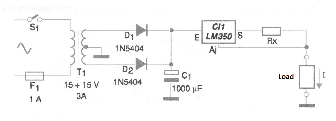
The current in the load depends on Rx and is calculated by the following formula:
I = 1.25 / Rx
The value 1.25 is given by the internal reference zener of the LM150 integrated circuit. The same circuit can be designed for currents up to 1.5 A using the LM317.
In figure 2 we have a suggestion of printed circuit board for implementation of this source.
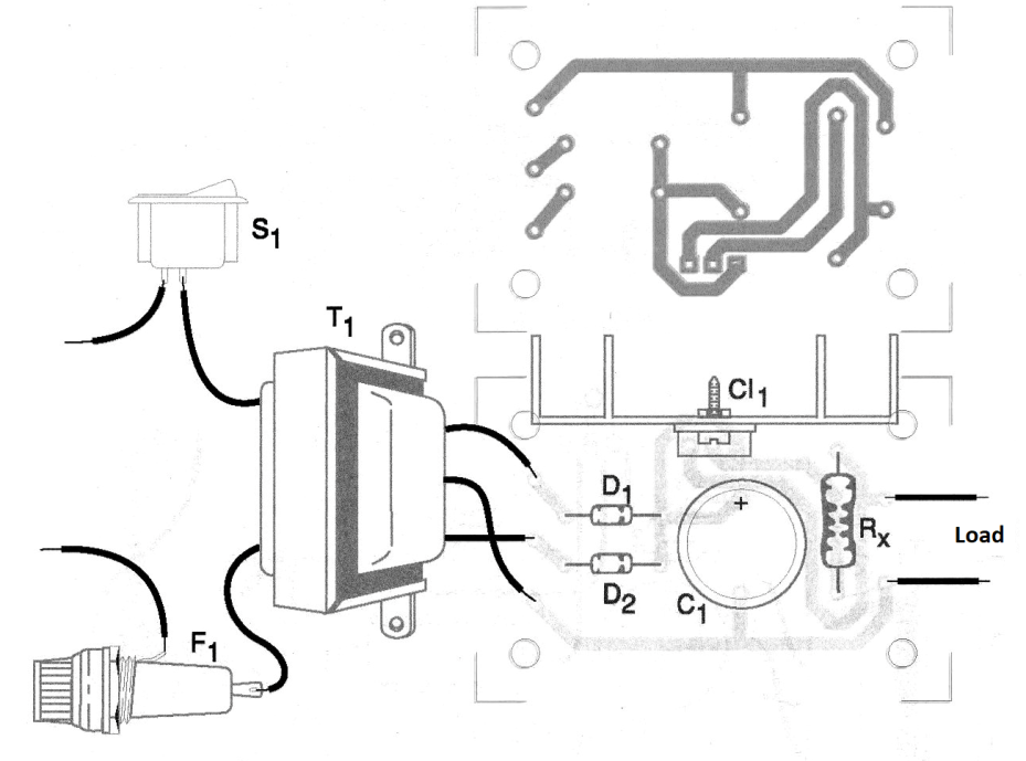
We remind you of the need to equip the integrated regulator circuit with a good heat sink and to adopt wide tracks to drive the most intense currents.
The transformer must have a secondary with a voltage at least 2 V higher than the maximum voltage that appears on the load under the constant current conditions. Note that the maximum input voltage of the LM350 is 35 V. In common applications such as battery charging, the filtration does not have to be the best, hence a relatively small value capacitor is used in this function.
An interesting change in the design is to connect a wire potentiometer with Rx to adjust the current intensity. A 50 ohm potentiometer provides a good range of settings.
Material list
CI-1 - LM350 (or LM317) - integrated voltage regulator circuit
D1, D2 - 1N5404 - Rectifier diodes
T1 - Transformer 15 + 15 V x 3 A - see text
Rx - Calculated according to desired current - see text
C1 - 1000 uF x 40 V - electrolytic capacitor
F1 - 1 A - fuse
S1 – On/Off switch
Several:
Printed circuit board, heat radiator, mounting box, fuse holder, wires, solder, etc.


