
Because of its versatility, low cost and the ability to generate rectangular signals between hertz fraction up to 500 kHz, the 555 is a solution most used in practical projects. In fact, the possibility of having 555 in CMOS and low voltage versions opens up a huge range of possibilities of applying this CI to the developer.
As an oscillator, the 555 is connected in the configuration shown in figure 5, where the formulas next to the diagram give the output times at the high and low level and from them the oscillation frequency.
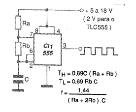
Ra and Rb can’t be less than 1 k ohm and the maximum recommended value given the instability that can be generated by leakage on the capacitor is 1 M ohm. For the capacitor, typical values are between 100 pF and 1500 pF. Too high values can unset the circuit if the component used is leaking.
The output of the 555 can drain or supply up to 200 mA but with inductive loads it is interesting to use a driver circuit. The active cycle of this circuit is greater than 50%. External resources such as the use of diodes for discharge can be used to modify the active cycle.
In figure 2 we have a suggestion of printed circuit board for the assembly of this oscillator.
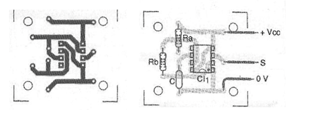
The power can be between 5 and 18 V typically, although there are versions that can operate with 1.5 V or less. The example circuit generates an audio signal of a few kilohertz.
Material list
CI-1 - 555 - integrated circuit
R1, R2 - 10 k ohm x 1/8 W - resistors
C1 - 47 nF - capacitor
Several:
Printed circuit board, wires, solder.


