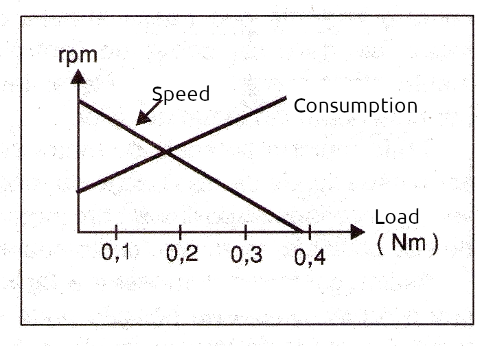
Direct current motors are devices whose power depends on the voltage applied to them and on the intensity of the current that flows through them. When we load a motor, its speed decreases and with this the intensity of the current increases, thus increasing the power it consumes, as shown in the characteristic curve in figure 1.
On the other hand, under constant load, the power consumed increases with the voltage in a more or less linear manner, together with the current and its rotation speed, as shown in the graph in figure 2.
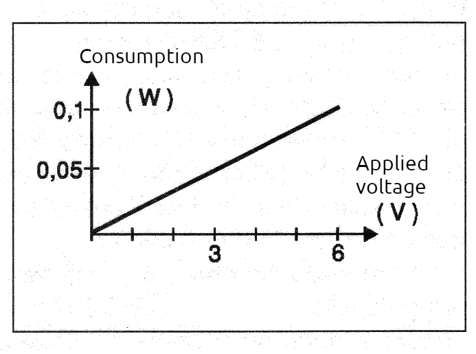
This means that the simplest way to control the speed of a direct current motor is by modifying the current that passes through it, which can be done with the help of some type of external device. This type of control in which we linearly vary the current applied to a load or the applied voltage is called "linear power control". There are several techniques to achieve this control, using everything from simple components to configurations based on modern semiconductors.
The Rheostat
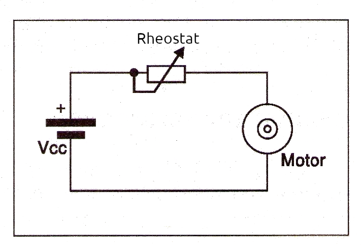
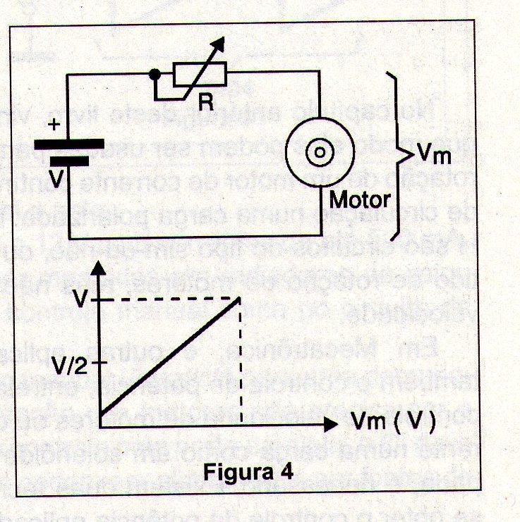
The simplest way to control the intensity of a current in a direct current motor is through a rheostat, as shown in Figure 3.
A rheostat is nothing more than a variable or adjustable resistor connected in series with the motor. When the rheostat is in its position of minimum resistance or zero, it passes freely and its intensity through the motor is maximum. When we increase the resistance of the rheostat, it forms a voltage divider with the motor. When its resistance increases, the voltage applied to the motor decreases and with it, the current also decreases. As the current in the motor decreases, the speed decreases, as shown in Figure 4.
Rheostats, however, have a serious limitation in their use: since the current that passes through them is the motor current, they must be able to control relatively intense currents and, more than that, they must be able to dissipate a good amount of heat.
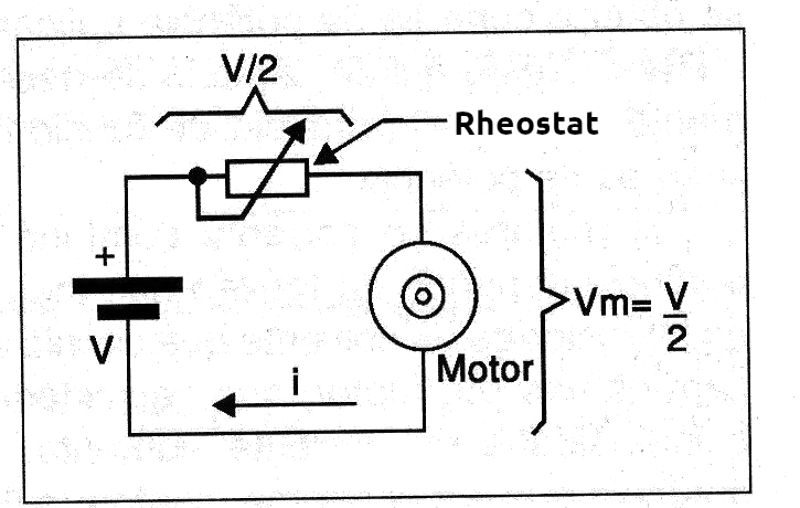
The greater the power of the controlled motor, the greater the rheostat's dissipation capacity must be. This makes it impossible to use these devices with high-power motors (or other loads), both due to cost and size. Thus, as shown in Figure 5, when the rheostat is in the position where the voltage applied to the motor is half the supply voltage, it dissipates as much power as the motor itself!
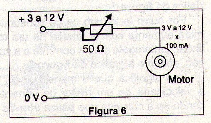
All this means that, even when controlling low-power motors, we need to use rheostats with good dissipation or current capacity. Rheostats are nothing more than potentiometers with only two terminals used, and in practical applications, we can use wire potentiometers with good dissipation. Thus, in Figure 6 we show how it is possible to use a 50-ohm x 5 W wire potentiometer to control a small DC motor that does not require more than about 100 mA.
For higher powers, using the rheostat in the indicated way is not recommended.
Using Transistors
We know that we can use transistors as switches and thus control strong currents from weak signals. The first important application of the transistor as a switch can be seen when we analyze H-bridges. However, transistors can also work in another way, amplifying the current that is, controlling its intensity through a load, which is exactly what interests us at this moment. When analyzing the operating principle of a transistor, we see that it can operate in a linear way, amplifying currents, that is, functioning as a variable resistor. Recalling through figure 7, the characteristic curve of a transistor has two important regions: one in which it operates as a switch and another in which it operates as an amplifier, that is, in linear mode.
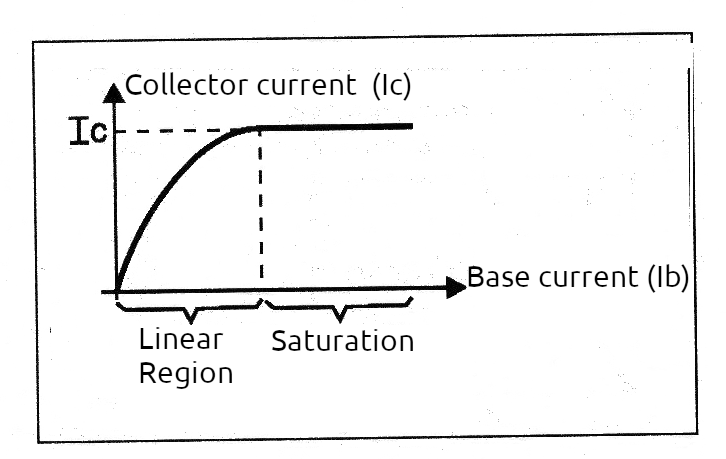
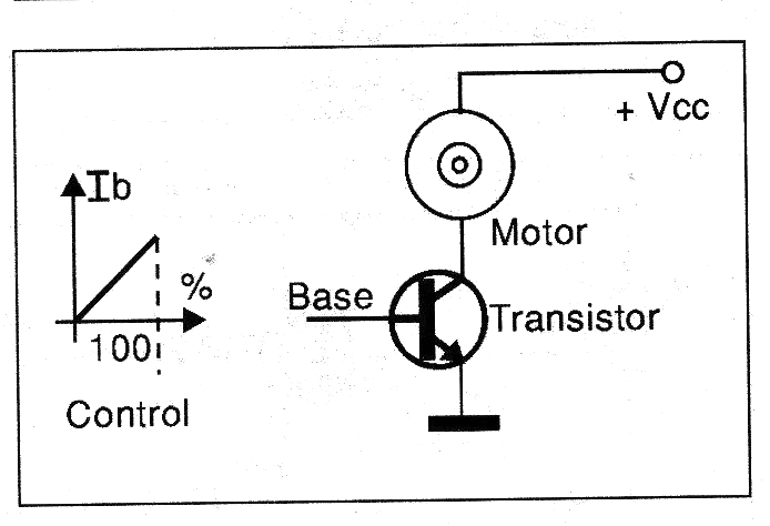
If we work with a transistor in the linear sector of its characteristic curve, we can precisely control the current that passes through it and a load connected in series, all from a much smaller current that we apply to its base, as shown in Figure 8.
Since a power transistor can control high currents, we can use a much lower current to control higher currents. This control current can be low enough for a common potentiometer to handle without problems. Putting this into practice, we can easily control the speed of a DC motor or any other load, using a low-power potentiometer and a transistor to do the “heavy lifting”. We then arrive at a first type of linear power control, which is shown in Figure 9. This circuit uses a power NPN transistor, which can be the BD135 for loads of up to 500 mA, the TIP31 for loads of up to 2 A, and the 2N3055 for loads of up to 4 amps.
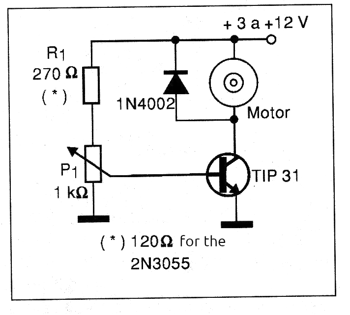
For the BD135 and TIP31 transistors, we can use a 1 k ohm wire potentiometer to control the speed of a motor with voltages up to about 12 V. For the 2N3055, we need to use a 470 ohm wire potentiometer to control loads with voltages up to about 20 V. We use wire potentiometers because, in conditions of lower resistance, even though the base current is less intense than that required by the motor, it still causes the component to heat up a bit. A carbon (graphite) potentiometer could overheat in a circuit like the one shown. Note that in all cases, the transistors must be mounted on good heat radiators.
The operation of this control is simple to understand: when the potentiometer cursor is on the emitter side of the transistor, the current in its base is practically zero and it remains in the cut-off position, that is, it does not conduct current. The motor does not receive current and remains stopped. This is the minimum power condition of the control.
As we move the cursor towards resistor R1, the base current increases smoothly and with it the current in the transistor collector increases, but multiplied. The collector current will be as many times greater than the base current as the transistor gain. With the increase in current, the motor accelerates until it reaches its maximum power. This increase in current continues until the point at which the transistor saturates, as shown in the graph in Figure 10.
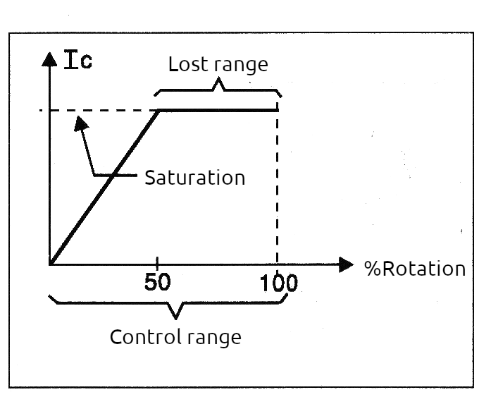
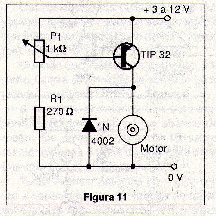
In an ideal situation, resistor R1 should be calculated so that this saturation occurs at the extreme (maximum) movement of the potentiometer cursor, but in practice this is not always possible, since transistors vary greatly in gain even among those of the same type (with the same numbering). Therefore, the best thing in a project like this is that, after assembly, the reader itself checks the point at which saturation occurs. If it is before the maximum rotation of the potentiometer, increase R1 and if it does not occur even when it reaches the end, decrease R1. This same circuit can be designed with PNP transistors, then acquiring the configuration shown in figure 11.
The transistor can be BD136 for 500 mA, TIP32 for 2 A and TIP2955 for 4 amps. The same considerations that we made for circuits with NPN transistors apply.
Darlington Circuits
In order to control the high currents of motors and other loads from even lower currents, we can combine several transistors and the most common configuration is called Darlington.
In figure 12 we have the way of connecting two NPN transistors in order to obtain a Darlington amplifier stage.
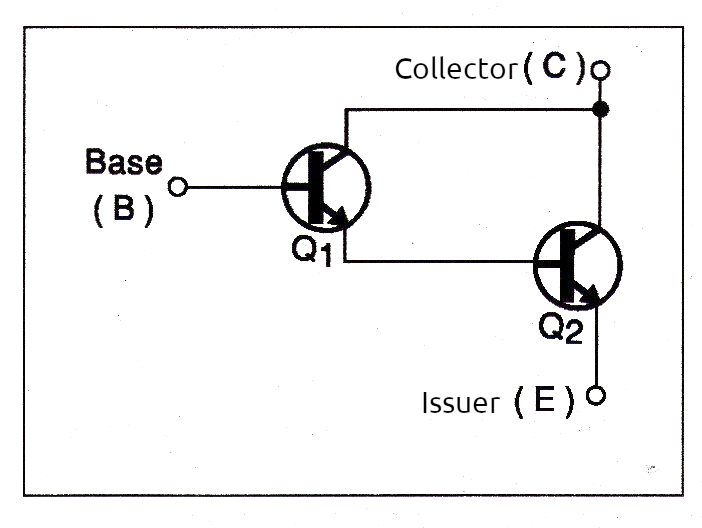
This circuit behaves like a single transistor whose gain is the product of the gains of the transistors used. For example, if Q1 has a gain of 200 and Q2 has a gain of 50, the circuit gain will be 50 x 200 = 000, that is, it will behave like a single transistor with a gain of 10,000. Therefore, to have linear power control using a circuit like this, we simply need to add the control device, which can be a potentiometer with a very high value, as shown in figure 13.
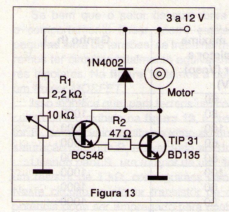
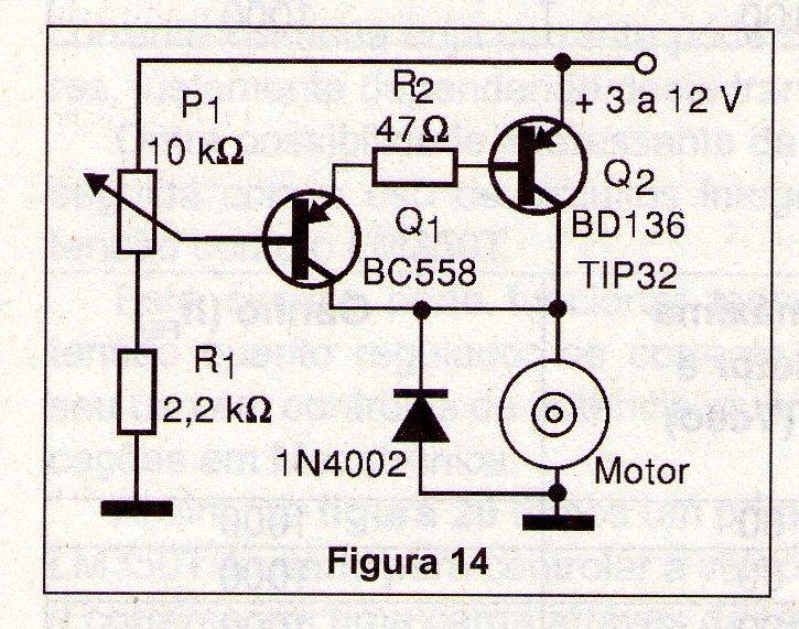
A 10,000-ohm potentiometer, as the one used in the circuit in Figure 13, passes a current of only 1 mA when supplied with 10 V. With this current, and with the transistors providing a gain of at least 1,000 times, we can control a load of up to 5 amps (1,000 x 0.001 = 1 A). See that under these conditions we no longer need a wire potentiometer on the control. A common low-dissipation (carbon) potentiometer will do just fine. For the circuit shown, with BC548 and TIP31 transistors we can control loads of up to 2 amps, without any problems. Transistors like the TIP41 instead of the TIP 31 can control even larger currents. The same configuration can be created with PNP transistors, as shown in Figure 14.
Darlington transistors
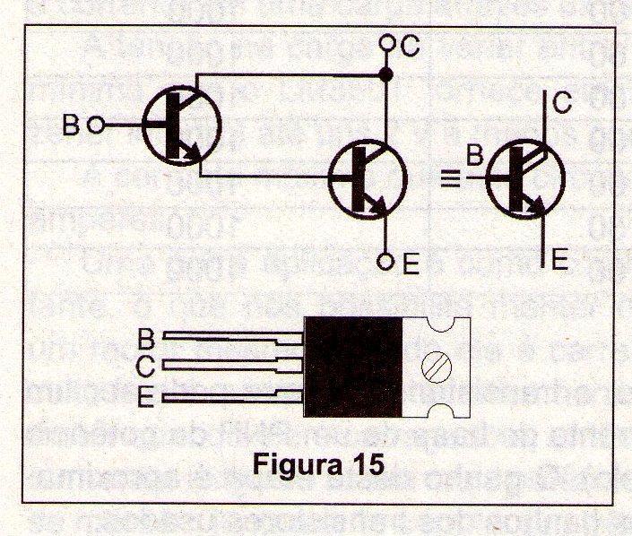
For the reader who wants to use this solution in the linear control of motors and other loads, there is an interesting alternative. There are components, which are actually formed by pairs of transistors already connected in the Darlington configuration, available in a single package.
These components are called "Darlington transistors" and typically have the equivalent circuit and appearance shown in Figure 15.
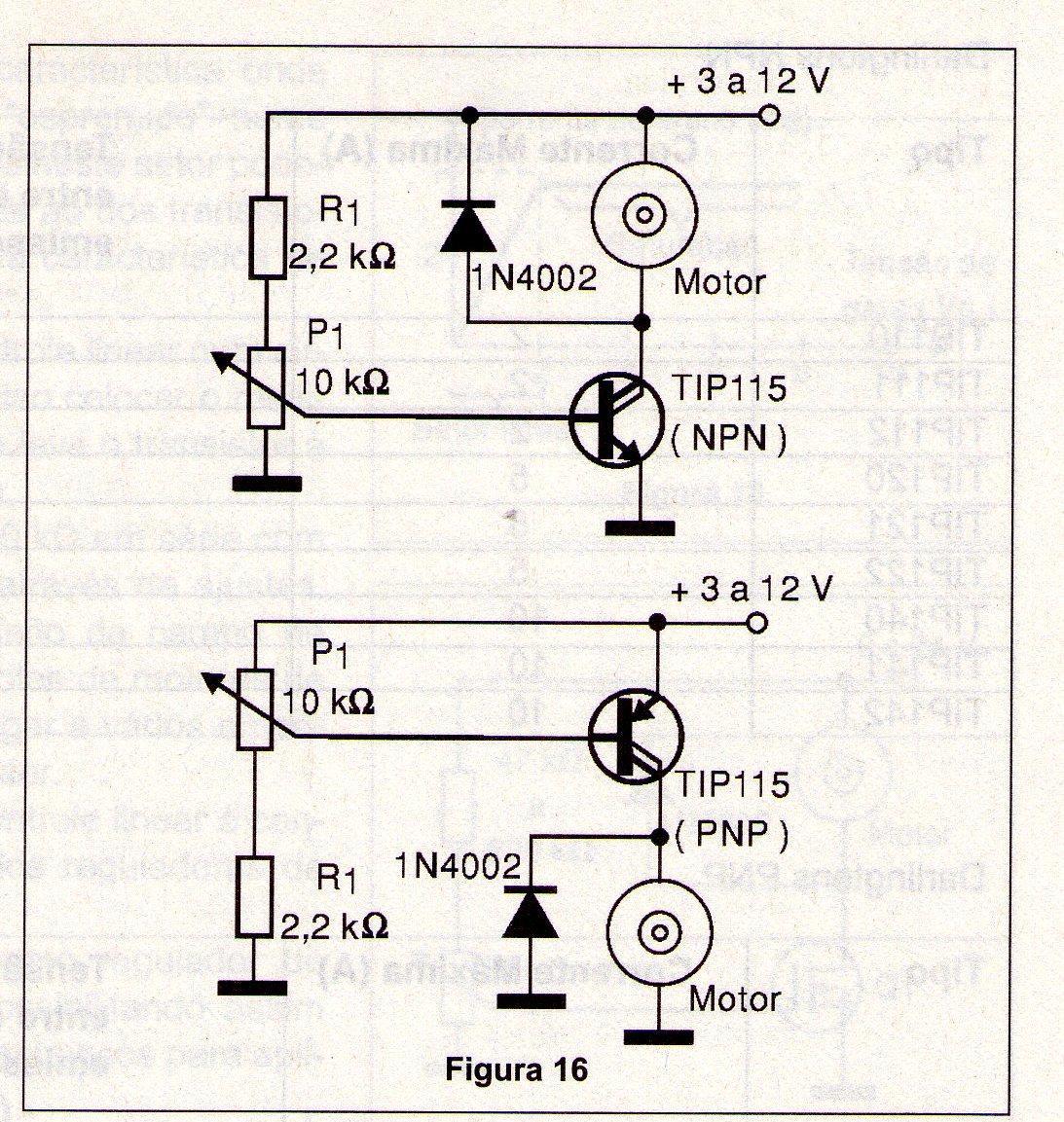
Texas Instruments manufactures an important series of high-power Darlington transistors, which are ideal not only for linear power controls but also for other applications, including the H-bridges that we studied in the previous article in this series. Figure 16 shows linear power controls with Texas TIP transistors, which can be either NPN or PNP.
The tables below give the characteristics of the transistors that can be used in these circuits:
NPN Darlingtons
| Type | Maximum Current (A) | Maximum voltage between collector and emitter (Vceo) - (V) | Gain (hFE) |
| TIP110 | 2 | 60 | 1000 |
| TIP111 | 2 | 80 | 1000 |
| TIP112 | 2 | 100 | 1000 |
| TIP120 | 5 | 60 | 1000 |
| TIP121 | 5 | 80 | 1000 |
| TIP122 | 5 | 100 | 1000 |
| TIP140 | 10 | 60 | 1000 |
| TIP141 | 10 | 80 | 1000 |
| TIP142 | 10 | 100 | 1000 |
PNP Darlington
| Type | Maximum Current (A) | Maximum voltage between collector and emitter (Vceo) - (V) |
Gain (hFE) |
| TIP115 | 2 | 60 | 1000 |
| TIP116 | 2 | 80 | 1000 |
| TIP117 | 2 | 100 | 1000 |
| TIP125 | 5 | 60 | 1000 |
| TIP126 | 5 | 80 | 1000 |
| TIP127 | 5 | 100 | 1000 |
| TIP145 | 10 | 60 | 1000 |
| TIP146 | 10 | 80 | 1000 |
| TIP147 | 10 | 100 | 1000 |
Other configurations
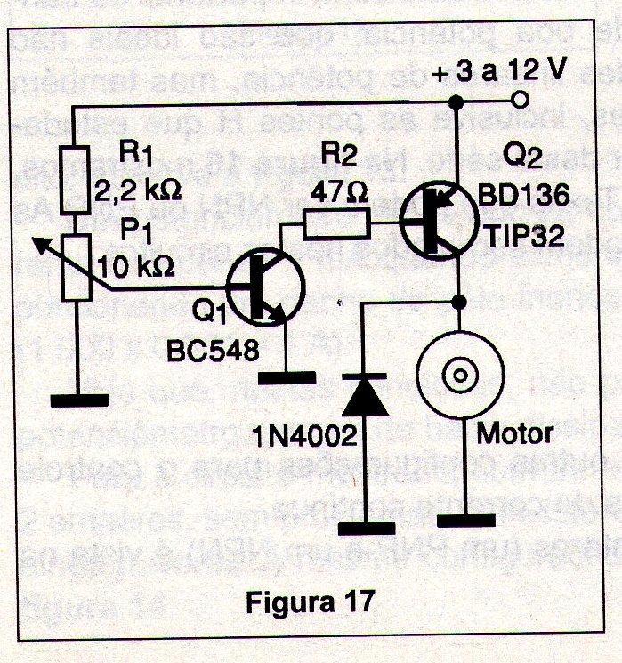
Common bipolar transistors can be used in other configurations for linear power control, such as the speed of DC motors. One possibility of using complementary transistors (one PNP and one NPN) is shown in Figure 17.
In this configuration, the NPN transistor (which can be a BC548) controls the base current of a power PNP (a TIP32, for example). The gain of this stage is approximately the product of the gains of the transistors used.
Other Components
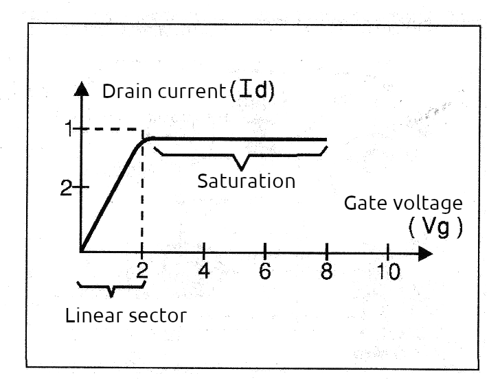
It is not only bipolar transistors that can be used in linear power control, with the basic configuration that we analyzed in this article. Other components that have linear operating characteristics at some point in their electrical behavior curve can also be used. One of them is the Power MOSFET or Power Field Effect Transistor. Although the sector of its characteristic curve in which linear behavior occurs is "squeezed" into a small voltage range, if we work in this sector we can have circuits that are totally equivalent to those of bipolar transistors. In figure 18 we have the characteristic curve of a Power MOSFET.
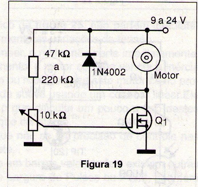
This means that, to have linear control in a circuit like the one shown in figure 19, it is necessary to set resistor R1 to a value very close to that which takes the transistor into saturation when P1 is fully open.
Using a 100 k ohm trimmer in series with a 1 k ohm resistor for R1, we can achieve this through adjustments. In this circuit, any power field effect transistor can be used to control direct current motors whose current can reach several amps, depending precisely on this transistor.
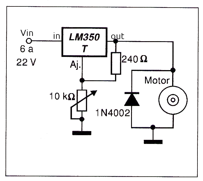
Another interesting possibility of linear mode control is achieved with the use of voltage regulator integrated circuits such as the LM350T. This circuit can function both as a voltage regulator and as a current regulator, thus enabling its use in power controls that are very interesting for mechatronics applications. Thus, in Figure 20 we have a first circuit in which the LM350T is used to control the speed of a motor or the current in a load through the applied voltage.
The voltage at the load will vary between 1.2 V (which is the minimum voltage that the LM350T provides at its output, due to the internal zener) to about 2 V less than the input voltage. The maximum current that this circuit can provide is 3 amps. Another application is as a constant current control, which allows us to maintain a constant torque of a motor even when it is loaded. What this circuit does is automatically increase the voltage applied to the motor when it is loaded and its current tends to increase, thus requiring more power. With this, the current is maintained together with the torque. Figure 21 shows how this can be done using the LM350T.
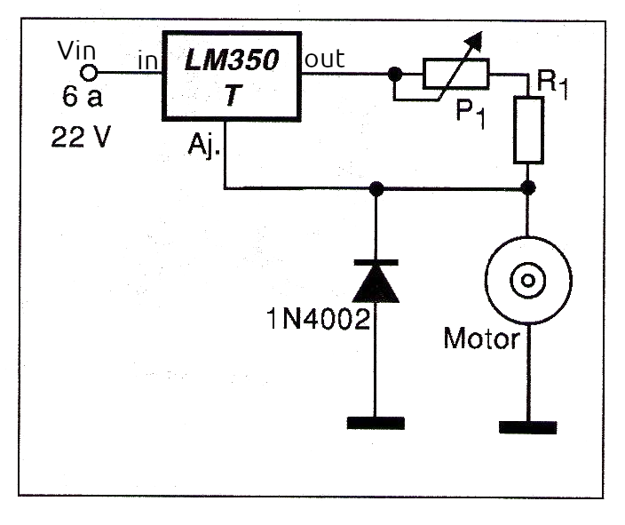
The current that will flow in the motor can be adjusted by P1 in a range that will have the maximum value dependent on R1. The formula to calculate R1 is:
R1 = 1.25/I
Where: R1 is given in ohms
I is the maximum current in amps in the motor
The minimum current depends on the value of P1 and will be given by:
I = 1.25/(R1+P1)
For example, for a 1 amp motor, we use R1 = 1.25 ohms.
Using a 100-ohm wire potentiometer the minimum current in the motor (maximum resistance position) will be:
I = 1.25/(1.25 + 100)
I = 1.25/101.25
I = 0.00123 A = 1.23 mA
Other three-terminal voltage regulators such as the LM117 can be used in the same way. The same formulas apply to calculations. We just note that the LM117 has a maximum output current of 1.5 A.
Using Sensors and Other Drive Modes
The most sensitive circuits we have seen in this article allow for the replacement of higher value potentiometers by resistive sensors of the same resistance. This means that some of these circuits can be used to control motors from light signals using LDRs or thermal sensors (NTCs) as sensors.
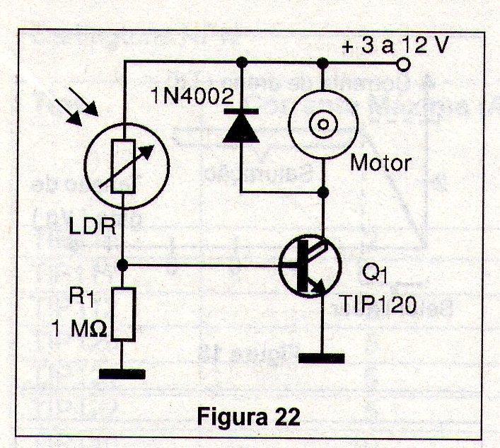
Pressure or position sensors can also be used, as long as the information sent to the circuit is in the form of a variable resistance. Figure 22 gives an example of a positive action power control by light intensity.
In this control, since the resistance of the LDR decreases with the intensity of the incident light, the current in the motor increases and with it its speed. We can have negative control using the configuration shown in figure 23.
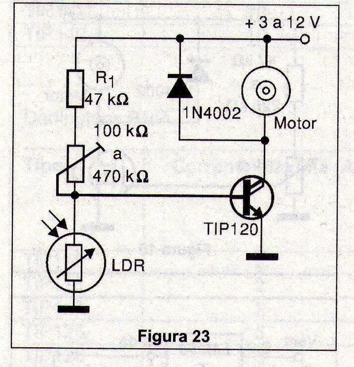
In this circuit, the current in the motor decreases when the intensity of the incident light on the sensor increases. The two circuits can serve as the basis for controlling robot movement based on the presence of light. Using the circuit in figure 2, for example, the robot slows down when it approaches an illuminated wall or any light source. The idea of a robot that has photophobia (fear of light) is something that can be easily implemented with this circuit. By adding a memory circuit, this circuit can be combined and thus obtain a certain “intelligence” for the robot, capable of memorizing light sources. One idea for using the circuits we analyzed with other drive modes is to mount sliding or even rotary potentiometers on pedals, as shown in figure 24.
With the settings shown in this figure, it is possible to control the speed of small DC motors using the feet.
Inertia
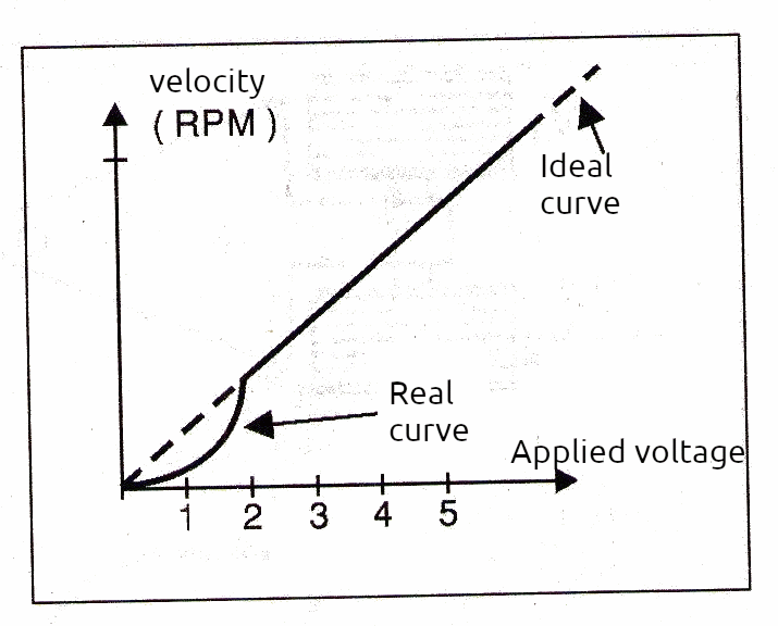
One of the problems that linear speed controls present when operating with DC motors is inertia. When supplied with a voltage that increases linearly from zero, as shown in the graph in Figure 25, the motors do not start immediately and do not maintain a speed that linearly follows the voltage variations.
When acting on the control (potentiometer) of a linear circuit, the motor does not start immediately. It is necessary to turn the control until, at a certain point, the motor is able to overcome the inertia and thus start at a certain speed. In a vehicle or robot that uses this motor as propulsion, this means that it is difficult to achieve a smooth start using a linear control. It starts with "jolts" or "gives a jolt" and then takes off, which makes it somewhat difficult to use these circuits in motion control that requires precision and constant torque. In the control of other automation systems, this possibility of not having control precision at low speeds can be a serious drawback for the project. To achieve better precision and more constant torque at low speeds, there are other techniques, such as the one that uses Pulse Width Modulation or PWM, which will be the subject of another article in this series.
Practical Projects
The projects given below are just simple suggestions that implement the controls we studied in this lesson. Obviously, readers can go much further, depending only on the level of knowledge they already have. Many of them are important for the didactic aspect since they can teach in practice what we learned from this article.
1. Robot Base
For the reader who wants to put into practice what we saw in this lesson, our suggestion is a robot or vehicle guided by wire with differential control. What we are going to do is a base with two motors and two reduction systems that are up to the reader, and can be used reduction boxes, direct coupling of the motor shaft to the wheel or belt, one on each side, as shown in figure 26.
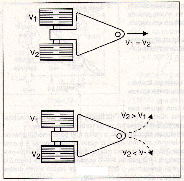
When we act on both motor controls, we can make them rotate at the same speed, and the vehicle moves in a straight line. By acting on one or the other potentiometer to increase or decrease the speed of the corresponding motor, we can make the vehicle go to the right or left, as shown in Figure 26. The circuit for the control is given in Figure 27.
Figure 27 – Complete direction and speed control circuit using two transistors and two reversible switches.
In Figure 28, we have the control assembly using a terminal bridge as a base, which is an ideal economical alternative for beginners. More advanced readers can do the same assembly using a printed circuit board.
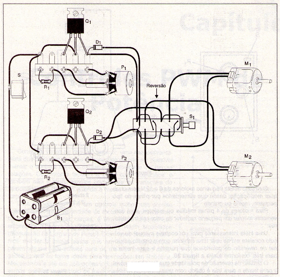
When assembling the terminal bridge, the reader must pay attention to the position of the transistors, because if they are inverted, the circuit will not work. The same applies to the position of the diodes. The purpose of the diodes is to protect the transistors against voltage spikes that are generated in the motor brushes when they operate. The circuit accepts small 6 to 12 V motors without any modification, as long as they are powered by small, medium or large batteries. For motors with 4 medium or larger batteries, it will be convenient to mount a small heat radiator on the transistors. An interesting idea for manual control of the vehicle is to use a small box with an additional polarity reversal circuit that allows it to go forward and backward, as shown in Figure 29.
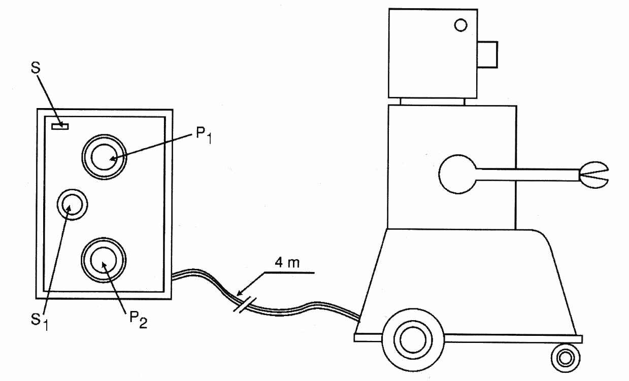
The polarity reversal circuit that makes the mobile base move forward and backward is obtained with a double HH switch. If this switch is not easily available on the electronics components market, we can adapt it using two common 2-pole x 2-position switches, gluing a piece of plastic or wood to their actuating elements so that they can be turned on at the same time.
Suggestion: how about making a combat robot based on this configuration!
Bill of Material
Q1, Q2 - TIP31 - power transistors
D1, D2 - 1N4002 - general purpose diodes
P1, P2 - 1 k ohms - linear potentiometers
R1, R2 - 220 ohms x 1/8 W - resistors (red, red, brown)
B1 - 4 to 8 small, medium or large batteries - according to motor voltage
M1, M2 - 6 to 12 V direct current motors - maximum current of 500 mA
S1 - 4-pole x 2-position switch - double HH - see text
Miscellaneous: wires, solder, terminal bridge, etc.

